BUILD YOUR FIRST ESP32 WIFI CONTROLLED ROBOT
FREEBOT is an open-source robot that aims to make robotics easy and affordable. In this article, I will show you how to build a wireless robot for just 1000 Rs. using cardboard, ESP32, and L298N motor driver. You will learn how to make the chassis from cardboard, how to connect the ESP32 and the motor driver, and how to control the robot using an Android app. This is a great project for beginners who want to learn robotics and IoT. You will also get to know the features and benefits of using an ESP32 and L298N motor driver for your robot projects.
Bill of Materials
| Item | Quantity | Buy |
|---|---|---|
| ESP32 Dev Board (Type-C) | 1 | Add to cart |
| L298N Motor Driver Module | 1 | Add to cart |
| BO / TT Gear DC Motor | 4 | Add to cart |
| BO Motor Wheel (65mm) | 4 | Add to cart |
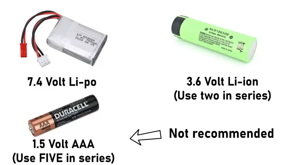
| 18650 Li-ion Battery (3.7V ) | 2 | Add to cart |
| Battery Holder (2 Cell) | 1 | Add to cart |
| Jumper Wires (Female-to-Female) | 2 x Strip | Add to cart |
| Jumper Wires (Male-to-Male) | 2 x Strip | Add to cart |
| 40-Pin Male Header Pins | 2 x Strip | Add to cart |
| 40-Pins Female Header Pins | 2 x Strip | Add to cart |
| Li-Ion Battery Charge | 1 | Add to cart |
| Single Side Prototype Board | 1 | Add to cart |
| USB Cable (Type-C) | 1 | Any Mobile Type-C cable |
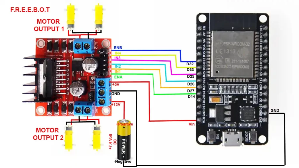
Circuit Explanation
| Motor driver pin | ESP32 pin used |
|---|---|
| ENA (left enable) | D14 (GPIO14) |
| IN1 (left dir A) | D27 (GPIO27) |
| IN2 (left dir B) | D26 (GPIO26) |
| IN3 (right dir A) | D25 (GPIO25) |
| IN4 (right dir B) | D33 (GPIO33) |
| ENB (right enable) | D32 (GPIO32) |
The battery provides power to the motor driver and the ESP32. The motor driver (L298N) uses that power to run the two DC motors while the ESP32 sends simple digital signals to the motor driver to tell it which direction to turn each motor and how fast (via PWM).
- Battery → supplies raw power for motors (higher current).
- L298N motor driver → takes the battery power and switches it to the motors; accepts logic-level control signals from the ESP32.
- ESP32 → the brain: sends direction and PWM speed signals to the L298N and receives network commands over WiFi.
- Motor power (on L298N):
- Connect the positive terminal of the battery (7.4 V in your diagram) to the L298N +12V / Vmotor input.
- Connect the battery negative to the L298N GND.
- ESP32 power (two common options):
- Option A — Power from battery via Vin on ESP32: Connect the same battery positive to the ESP32 Vin if your board supports that input voltage and you trust it. Also connect the battery negative → ESP32 GND.
- Option B — Power ESP32 from a regulated 5V (safer): Use a 5V regulator or the L298N’s onboard 5V regulator (if present and enabled with a jumper) to feed the ESP32’s 5V or USB input. Then connect that regulator ground to the battery negative.
- Common ground is mandatory:
- Connect L298N GND, ESP32 GND, and battery negative all together. If the grounds are not common, the logic signals from the ESP32 will not be referenced properly, and the motors may not respond.
Safety tip: Don’t connect/disconnect motors while the battery is connected. Double-check polarity reversing battery wires can damage components.
4Motor driver pins and what they do (L298N)
- +12V (Vmotor): battery positive → powers motors.
- GND: common ground.
- +5V (logic supply): some L298N boards include a 5V regulator output. If you place a jumper, it will supply 5V logic from the motor supply; otherwise, you must provide a separate 5V logic supply for the motor driver’s internal logic.
- ENA / ENB (enable pins): when HIGH, the corresponding motor channel is enabled. These pins accept PWM for speed control.
- IN1 / IN2 / IN3 / IN4 (direction pins): digital inputs that determine motor direction:
- IN1=HIGH, IN2=LOW → left motor forward (example)
- IN1=LOW, IN2=HIGH → left motor backward
- Similarly, IN3/IN4 controls the right motor
The ENA/ENB pins are where you send PWM (analogWrite) from the ESP32 to control motor speed. The INx pins are digital — set them HIGH or LOW to change motor direction.
Signal flow example
- You send a UDP command
f,100from your phone/PC. - ESP32 receives that packet and sets
dataParser.getField(0)to"f"and speed to100. - ESP32 calls
forward(100, 100)in code:- Sets left IN1=HIGH, IN2=LOW and right IN3=HIGH, IN4=LOW (direction = forward).
- Sends PWM value
100to ENA and ENB (speed).
- L298N applies battery voltage to motors with correct polarity and duty cycle — motors spin forward at the set speed.
PWM speed control explained
- PWM (Pulse Width Modulation) is like turning a light switch on/off rapidly. If it’s on half the time and off half the time, the motor gets “half power” on average — that’s slower.
- The ESP32 writes PWM to the ENA/ENB pins. Bigger PWM number → more on-time → faster motor.
Problems and fixes
- Motors don’t respond: check the common ground and battery voltage. Confirm ESP32 and L298N share ground.
- ESP32 resets when motors run: that usually means the battery’s voltage drops under motor load. Use a battery with enough current capability and add capacitors or a separate regulator for the ESP32.
- Motors run only one way or twitch: check the digital IN wiring for swapped pins or short circuits.
Testing steps (do this before final assembly)
- No motors connected: Upload code and check ESP32 connects to WiFi (Serial Monitor shows IP).
- Confirm control signals: With motors still disconnected, observe the EN/IN pins with a multimeter or LED to ensure toggling when commands are sent.
- Connect motors and battery: Put the robot on blocks (so wheels spin freely) and send small speed commands first (e.g.,
f,60). Watch behavior. - Increase speed gradually and observe for overheating or voltage drops.
Code Explained
The code for this project is really simple. If you know high school-level programming, you should be good to go. Let’s go step-by-step through the code and see how each part helps our ESP32 robot move, connect, and understand commands.
Download code from GitHub
Including the Required Libraries
#include <WiFi.h>
#include <AsyncUDP.h>
#include <Arduino.h>
#include "DataParser.h"Think of libraries as “superpowers” we give to our ESP32.
- WiFi.h → helps the ESP32 connect to your home WiFi network.
- AsyncUDP.h → allows it to send and receive data packets quickly over the network (we use UDP because it’s lightweight and fast).
- Arduino.h → gives access to the core Arduino functions like
digitalWrite(),pinMode(), andanalogWrite(). - DataParser.h → a custom helper library to split incoming CSV data like
f,80into separate fields (command =f, speed =80).
Before uploading the code, make sure you’ve got the right tools in your Arduino IDE.
- Install ESP32 Board Support:
- Go to File → Preferences → Additional Board Manager URLs
- Add:
https://dl.espressif.com/dl/package_esp32_index.json - Then go to Tools → Board → Boards Manager
Search for ESP32 and click Install.
- Install Libraries:
- Go to Sketch → Include Library → Manage Libraries…
- Search and install:
- AsyncUDP (usually comes with ESP32 core)
- WiFi (also built-in)
- DataParser (you can include your custom
.hand.cppfiles in your project folder)
Setting Up WiFi Credentials
const char* ssid = "Askey5100-02B0";
const char* password = "HHLUnKLKQW";Here, you enter your WiFi name and password so your ESP32 can join the network just like how your phone connects to WiFi. Replace these with your own WiFi credentials before uploading the code!
Motor Driver Pins
int in1=27, in2=26, ena=14;
int in3=25, in4=33, enb=32;These are the control pins connected to your motor driver module (like L298N or L293D).
- The IN1/IN2 pins control the direction of the left motor.
- The ENA pin controls the speed of the left motor using PWM (Pulse Width Modulation).
- Similarly, IN3/IN4 and ENB control the right motor.
Think of it as: “ENA is the accelerator, IN1 and IN2 are the steering directions.”
Connecting to WiFi
WiFi.begin(ssid, password);
while (WiFi.status() != WL_CONNECTED) {
  delay(1000);
  Serial.println("Connecting to WiFi...");
}
Serial.println("Connected to WiFi");When the ESP32 starts, it tries to connect to the WiFi network you provided. It keeps checking the connection status until it’s successful. Once connected, you’ll see “Connected to WiFi” in the Serial Monitor.
Setting Up UDP Communication
if (udp.listen(udpPort)) {
  Serial.print("UDP Listening on IP: ");
  Serial.println(WiFi.localIP());
  udp.onPacket([](AsyncUDPPacket packet) {
    String IncomingData = (char*)packet.data();
    dataParser.parseData(IncomingData, ',');
    Speed = (dataParser.getField(1)).toInt();
    Left_speed = Speed;
    Right_speed = Speed;
  });
}This part is like setting up the walkie-talkie for your robot.
- The ESP32 starts listening for messages sent over the local network on a specific UDP port (12345).
- When a packet arrives (like
f,100), it’s split into two pieces:f= command (forward, backward, left, right, stop)100= speed value
- The robot updates its internal variables to match these commands.
Main Loop
if(dataParser.getField(0) == "f") forward(Left_speed, Right_speed);
if(dataParser.getField(0) == "b") backward(Left_speed, Right_speed);
if(dataParser.getField(0) == "l") left(Left_speed, Right_speed);
if(dataParser.getField(0) == "r") right(Left_speed, Right_speed);
if(dataParser.getField(0) == "s") Stop();This is where your ESP32 thinks.
It keeps checking what command it received and calls the matching function.
So if you send "f,120" → The robot moves forward at a speed 120.
Movement Functions
These functions make the robot move. Let’s look at how each movement is controlled.
Forward Motion
void forward(int left_speed, int right_speed) {
  digitalWrite(in1, HIGH);
  digitalWrite(in2, LOW);
  digitalWrite(in3, HIGH);
  digitalWrite(in4, LOW);
  analogWrite(ena, left_speed);
  analogWrite(enb, right_speed);
}This sets the motor pins so both wheels spin forward.
Backward
void backward(int left_speed, int right_speed) {
  digitalWrite(in1, LOW);
  digitalWrite(in2, HIGH);
  digitalWrite(in3, LOW);
  digitalWrite(in4, HIGH);
  analogWrite(ena, left_speed);
  analogWrite(enb, right_speed);
}Reverses the motor direction.
Left Turn
void left(int left_speed, int right_speed) {
  digitalWrite(in1, HIGH);
  digitalWrite(in2, LOW);
  digitalWrite(in3, LOW);
  digitalWrite(in4, HIGH);
  analogWrite(ena, left_speed);
  analogWrite(enb, right_speed);
}Left motor moves forward, right motor backward → the robot rotates left in place.
Right Turn
void right(int left_speed, int right_speed) {
  digitalWrite(in1, LOW);
  digitalWrite(in2, HIGH);
  digitalWrite(in3, HIGH);
  digitalWrite(in4, LOW);
  analogWrite(ena, left_speed);
  analogWrite(enb, right_speed);
}Same logic but swapped spins right.
Stop
void Stop() {
  digitalWrite(in1, LOW);
  digitalWrite(in2, LOW);
  digitalWrite(in3, LOW);
  digitalWrite(in4, LOW);
  analogWrite(ena, 0);
  analogWrite(enb, 0);
}All motors OFF, robot stops
Checking WiFi Connection
Once you upload the code, turn on the wifi hotspot. Install the Android app on the phone and connect to the same wifi network.
- Open Serial Monitor at 115200 baud.
- Wait for the message:
Connecting to WiFi... Connected to WiFi UDP Listening on IP: 192.168.x.x - Note down that IP address — you’ll use it from your mobile or PC to send UDP commands like
f,100ors,0.
How to control the Robot
Now that your ESP32 robot is powered up, coded, and connected to WiFi, it’s time for the fun part: driving it!
You’ll be using an Android app that sends commands (like forward, left, stop) to the ESP32 over WiFi using UDP packets.
Install the Android App
- Copy the provided
.apkfile from your project folder onto your Android phone. - Open the file and install it (you might need to allow installation from unknown sources).
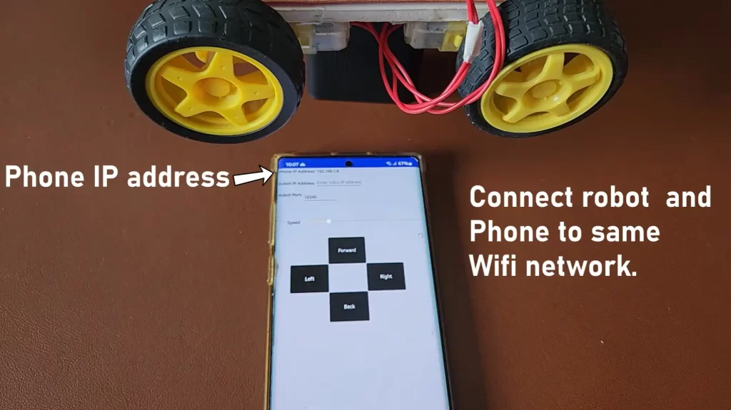
- Once installed, open the app you’ll see a screen similar to this: Refer to the image above. The app has:
- Text boxes for Phone IP Address, Robot IP Address, and Port
- A Speed Slider
- Direction buttons — Forward, Back, Left, Right, and Stop
Connect to the Same WiFi Network
Both your phone and robot (ESP32) must be connected to the same WiFi network.
This is crucial; they talk to each other over your home WiFi, not through the internet.
Find Your Robot’s IP Address
- Connect your ESP32 to your computer and open the Serial Monitor in Arduino IDE.
- Set the baud rate to 115200.
- After a few seconds, you should see something like this:
Connecting to WiFi... Connected to WiFi UDP Listening on IP: 192.168.1.8 - The IP address after “UDP Listening on IP” (for example, 192.168.1.8) is your robot’s IP address.
Configure the App
Now open the Android app and fill in the details:
| Field | What to Enter | Example |
|---|---|---|
| Robot IP Address | The IP address from Serial Monitor | 192.168.1.8 |
| Robot Port | Always use 12345 | 12345 |
Note: The port number must match the udpPort value in your ESP32 code. If you change it in the code, make sure to update it here too.
Drive the Robot
- Use the Forward, Backward, Left, and Right buttons to control the movement.
- The Speed Slider lets you adjust how fast the motors spin.
- Tap Stop to halt the robot immediately.
Behind the scenes, every button press sends a small message to the ESP32
f,120   → move forward at speed 120
b,100   → move backward at speed 100
s,0 → stop the motorsYour ESP32 receives this packet, decodes it, and runs the right function from your code (forward, backward, etc.).
Once it works, place your robot on the floor and try out different speeds. Notice how quickly it responds. That’s the beauty of UDP communication: fast, light, and perfect for real-time control.
Conclusion
This is the first part of this project. Here, we mostly worked on the robot itself. Next, we will add computer vision, Ball following, and Hand tracking.