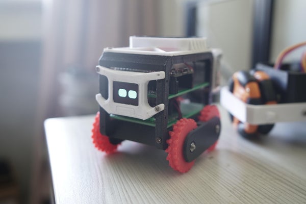
ESP32 ROBOT WITH ODOMETRY AND WAYPOINT NAVIGATION
CAKE is an ESP32-based robot capable of odometry, waypoint navigation, and mapping its area. It has encoders and an IMU sensor, which helps the robot calculate its position using odometry. The robot also has a Tof sensor, which, when combined with the IMU, can make a map of the local area.
This project started as a learning exercise for me. I wanted to learn more about SLAM and robot navigation. Most tutorials are just ROS and lidar. I did try it, I made a robot using the ROS navigation stack, it worked, but it didn’t satisfy my curiosity.
To simply put it wasn’t sexy enough. There was no pain, and I love pain. I was more interested in the math and raw engineering. The joy of figuring things out myself. I read some papers on SLAM and robot navigation, and it turns out it is just basic math and high school trigonometry. If you know about angles, basic algebra, and matrices, you are good to go.
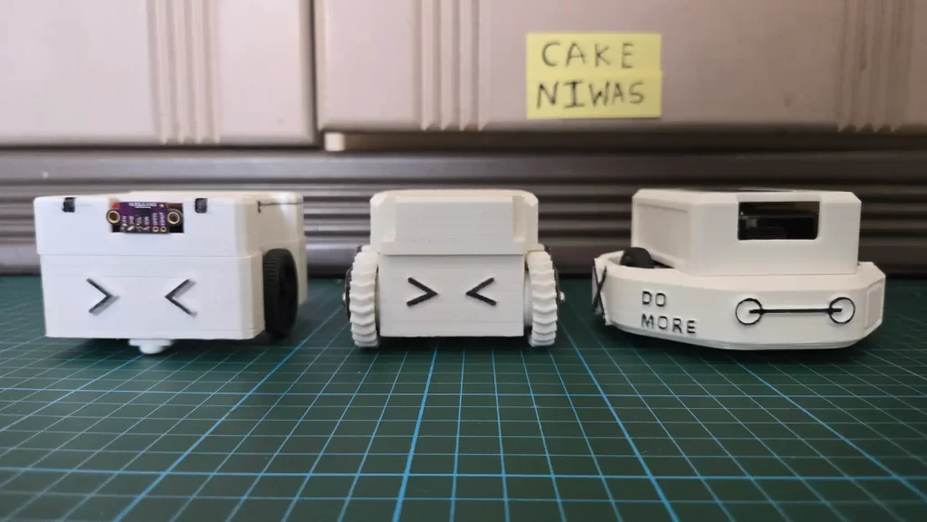
So I challenge myself to build a robot that is easy to build, has affordable parts, and inspires people about science and engineering. I have been working on this project for more than a year now. I tried different designs and parts. The first robot I built with odometry was Always Calibrate -II I never released any tutorial on it. It’s too expensive to build; you might have seen it on my Instagram. Then I built SLIDE omnidirectional robot that didn’t have odometry but had waypoint navigation. Learning from these two projects helped me create the CAKE series 🙂
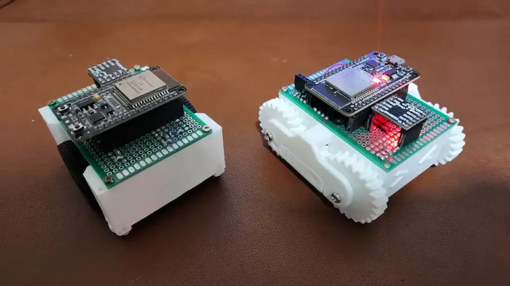
CAKE is printed in PLA with a 0.28mm layer height. There are several variants of this project. My favorites are Cake and Pancake. Cake uses angled N20 motors, which are expensive and hard to source. Pancake has normal N20 motors and is bigger in size. They both use the same electronic components and code even the working is also the same. In this tutorial, we will use Pancake, but all of this will also apply to other variants. Basically, they are all internally the same, just the chassis is different.
Along with this article, I have made several YouTube tutorials for this project. I hope this helps you.
Bill Of Materials
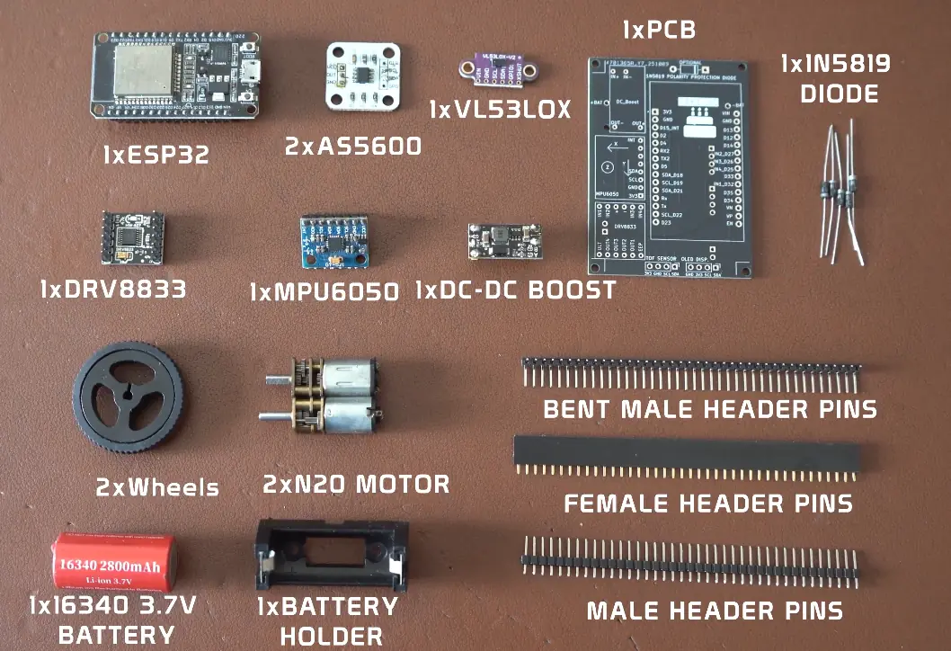
Welcome to the expensive part of this project sourcing parts 🙂 You can order 3D printed parts and some electronics from me, or message me on WhatsApp or Instagram.
My goal was to make this project accessible to all. All the components used in the project are off-the-shelf and very common. I would recommend first trying to get them from a local shop, then trying an online marketplace. I have used modules instead of IC’s this will allow you to recycle these parts for other projects.
| Component | Quantity | Description |
|---|---|---|
| ESP32 Dev Board | 1 | Main microcontroller |
| DRV8833 Motor Driver | 1 | Dual motor driver breakout board |
| N20 Gear Motor | 2 | Compact DC motors |
| AS5600 Encoder | 2 | Magnetic encoder for motor position feedback |
| MPU6050 Module | 1 | 6-axis IMU (accelerometer + gyroscope) |
| VL53L0X ToF Sensor | 1 | Time-of-flight distance sensor for obstacle detection |
| DC Boost Module | 1 | MT3608 voltage booster (e.g., 3.7V to 5V) |
| 16340 Battery | 1 | Rechargeable Li-ion battery for powering the system |
| Battery Holder | 1 | Compatible holder for 16340 battery |
| 1N5819 Diode | 1 | Schottky diode for reverse polarity protection |
| Male Pin Headers 90 degree | 40 pins | 2.54mm pitch, for module and I/O connections |
| Female Pin Headers | 40 pins | 2.54mm pitch, for module and I/O connections |
| 2mm x 10mm Screws | 20 | For mounting the PCB and motors |
| Wires | — | Flexible hookup wires for connections |
| Soldering Iron Set | 1 | Basic soldering kit for assembly and repair |
| 3D Printed parts | 1 | For mounting PCB and motors |
Electronics and Wiring
Welcome to the technical part of this project. Lots of soldering and coffee. Don’t worry, I will guide you to take your time and be happy. I have explained each electronic part in detail in the sections below; however, if there are still difficulties, try searching on YouTube. These are very common parts; there are tons of tutorials available online.
I made a full circuit diagram with everything in it. It was too confusing, so I decided to make several smaller diagrams. Wiring for each component has been explained separately. Once you wire them separately, it should automatically complete the full wiring for the robot. Don’t worry if some sensors are connected to the same pins, like encoder, Tof, and IMU. This is ok, they use I2C for communication. A full circuit diagram PDF is also available with PCB files.
Understanding the 16340 Li-ion Battery
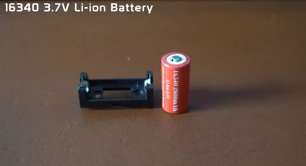
Our ESP32 robot runs on a single 16340 Li-ion battery, a compact yet powerful energy source that keeps the motors spinning and sensors alive. Despite its small size, this little cell can store a decent amount of charge and deliver enough current for most small robotics projects. I used a 2800mAh battery, which gave me a runtime of 15 minutes per charge
The number 16340 actually tells you its size: 16 mm in diameter and 34 mm in length, similar to a shorter version of an AA battery. Inside, it uses lithium-ion chemistry, the same kind you’ll find in phones and laptops. That means it offers high energy density and can be recharged hundreds of times if handled correctly.
Typical specifications:
- Nominal Voltage: 3.7 V
- Fully Charged Voltage: 4.2 V
- Discharged Voltage: around 3.0 V (don’t go below this)
- Capacity: usually between 600–1200 mAh, depending on the brand
Because the ESP32 and other parts of the robot need a stable 5V, we use the DC-DC boost converter to step up the battery voltage. The Li-ion cell on its own isn’t enough to keep everything running at a constant voltage, especially as it discharges.
Battery Holder and Polarity
In this project, the battery sits in a 16340 holder, which makes it easy to replace or recharge the cell. The holder has clear ‘+’ (positive) and ‘–’ (negative) markings, and you’ll see matching symbols printed on your PCB. It’s crucial to match these markings when soldering the holder onto the board and when inserting the battery later.
If you accidentally reverse the polarity, current will flow in the wrong direction, potentially damaging the circuit. That’s why we added the 1N5819 protection diode, just in case. Still, prevention is better than protection, so always double-check orientation before inserting the cell.
If there is any difficulty in sourcing this battery, you may also use its bigger cousin 18630 Li-ion battery. It works the same, but is bigger in size; it won’t fit on the chassis and will look ugly, but he is a good person, don’t judge him, he will give his best to power your robot. Be gentle with them both. You can also use Li-po, just make sure it’s a single-cell 3.7- 3.7-4.2V
Safe Handling Tips
- Never short the battery terminals.
- Use only Li-ion compatible chargers.
- Avoid fully discharging the cell; it shortens its life.
- Store it in a cool, dry place when not in use.
Understanding the 1N5819 Protection Diode
The 1N5819 is basically a “bodyguard” for your robot’s electronics. Every good robotics project needs a bit of built-in safety, and that’s exactly the job of the 1N5819 protection diode in your ESP32 robot. Since this robot doesn’t have an on/off switch, power goes directly from the battery to the circuit. That makes things simple but also risky. If the battery is accidentally connected in reverse, current will flow the wrong way, and that can instantly damage your ESP32, boost converter, or sensors.
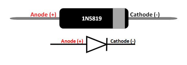
The 1N5819 acts like a one-way valve for electricity. It allows current to flow only in the correct direction from the battery’s positive terminal toward the rest of the circuit and blocks it if the polarity is reversed. So, if you ever connect the battery backward, the diode stops the current flow and prevents you from frying your components.
This diode is a Schottky diode, which means it has a very low forward voltage drop (around 0.2V to 0.3V). In simple terms, it doesn’t waste much energy as heat while doing its job. That’s why it’s commonly used in battery-powered electronics and Arduino/ESP32 robotics projects where efficiency matters.
How It Works in the Circuit
- When the battery is connected correctly, current flows through the diode to power the entire system.
- If the battery is connected the wrong way, the diode blocks the current completely, protecting the rest of the circuit.
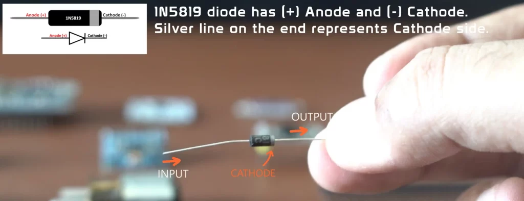
Soldering and Orientation
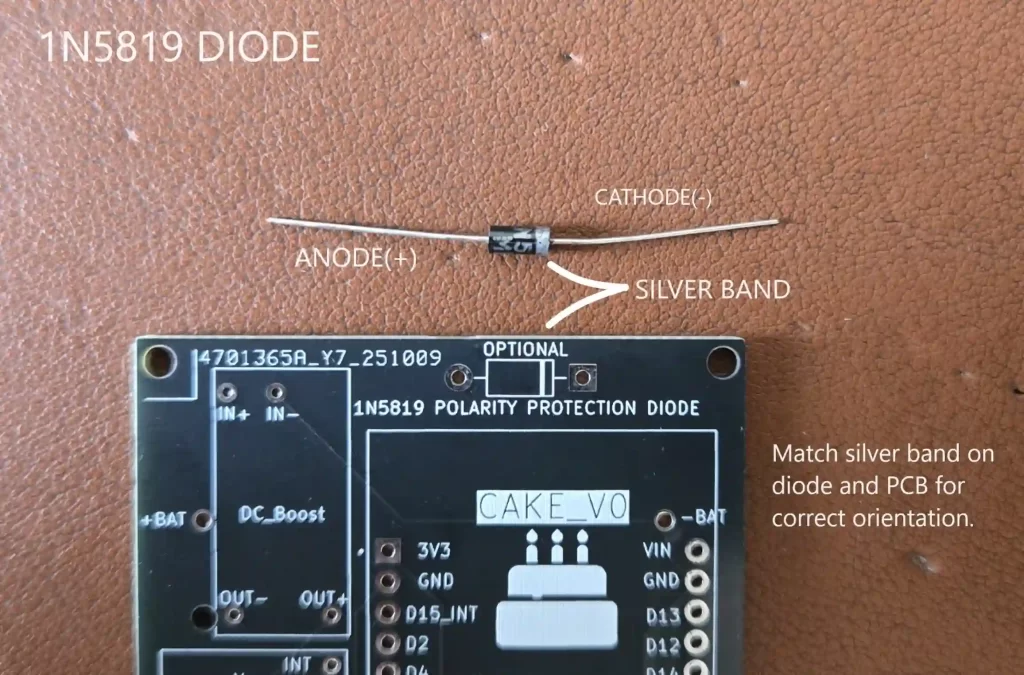
When you solder the 1N5819 on your PCB, you’ll notice that one end of the diode has a silver band. That’s called the cathode side. The PCB should also have a similar marking (a line or band) printed next to the diode’s footprint. You must align the diode’s silver band with the marking on the PCB before soldering. If you place it the other way around, the current won’t flow correctly, and your robot won’t power up. I have shown this in the tutorial video here.
| Pin/Side | Label |
|---|---|
| Plain end | Anode |
| Silver-banded end | Cathode |
By adding this small but essential diode, we are giving the robot a much-needed layer of protection. I know most of the people reading this article are new to robotics. I just want to save you from the pain of smelling burned electronics :).
Understanding the DC-DC Boost
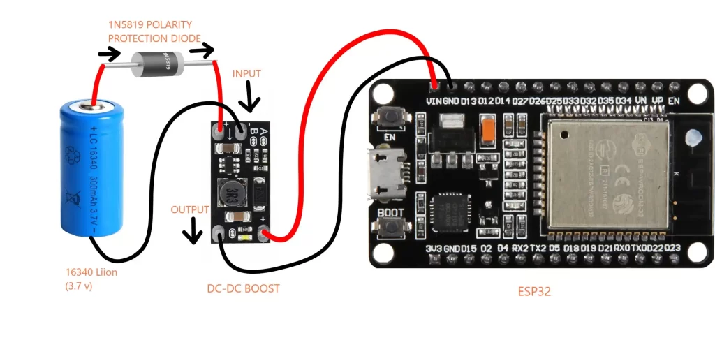
Every robot, no matter how fancy, needs a reliable power source. In our case, the robot runs on a single 16340 Li-ion rechargeable battery. A full battery gives about 4.2 volts, and as it discharges, that drops closer to 3 volts. Unfortunately, our ESP32 and other parts, like motor drivers, prefer a clean 5 volts to run properly. That’s where the DC-DC boost converter comes in. It takes whatever voltage your battery provides and “boosts” it up to the level your circuit needs.
A/B Jumpers
There are no buttons or dials on the boost module to set the voltage; instead, there are two solder pads labeled A and B. These act like settings that tell the module how to behave. By default, both are connected, so the output voltage is set to 12V. Do not connect to your robot in this configuration; otherwise, you will blow up the board. Instead, we will set the voltage to 5V using the following table. Follow here
Here’s a quick table that shows what each jumper setup does:
| Jumper Configuration | What It Means | Output Voltage |
|---|---|---|
| A and B connected (default) | Standard setup | 12V |
| Break A, keep B | Fine-tuning mode | 8V |
| Break B, keep A | High-voltage mode | 9V |
| Both A and B broken | Custom mode (for external resistors) | 5V |
For our ESP32 robot, we only need 5V, so we’ll break both A and B connections. Always adjust the voltage before connecting the ESP32; too much voltage can instantly burn the board, and that’s a sad way to start a robotics project. Don’t worry, you’re not “breaking” the module permanently—you’re just opening up that connection so it uses a different feedback path inside.
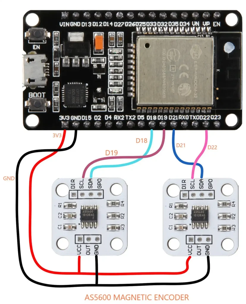
Understanding the AS5600 Magnetic encoder
To track the movement of the robot, we need to know how far each wheel has turned. That’s where the AS5600 magnetic encoder comes in. It’s a tiny sensor that measures the rotation of a magnetic field. When you attach a small magnet to your motor shaft, the AS5600 detects its angle as it spins, giving you accurate feedback for speed and distance. This is the basis of odometry in robotics. We will use the wheel’s angle to track how far each wheel has moved, then by using some good good maths we will be able to calculate the path of the robot. Odometry calculations are explained here
| Feature | Specification |
|---|---|
| Sensor Type | Contactless magnetic rotary encoder |
| Resolution | 12-bit (4096 positions per revolution) |
| Output Interfaces | Analog, PWM, I²C |
| Operating Voltage | 3.3 V to 5.5 V |
| Measurement Range | 0° to 360° absolute angle |
| Interface Protocol | I²C (up to 1 MHz) |
The AS5600 doesn’t actually touch the magnet. Instead, it uses a Hall-effect sensor array to sense the direction of the magnetic field. As the magnet rotates, the sensor calculates the angular position and converts it into a digital value. That means no mechanical wear, no friction, and no noisy signals, just smooth, precise readings.
Pins and Connections
| Pin | Function |
|---|---|
| VCC | Power supply input (3.3 V to 5 V) |
| GND | Ground |
| SDA | I²C data line for communication |
| SCL | I²C clock line for communication |
| OUT | Analog or PWM output(Not connected) |
| DIR | Direction control for output signal(Not connected) |
| PWM | Optional PWM output (some modules only)(Not connected) |
| NC | Not connected (may vary by board)(Not connected) |
The sensor board usually comes with several pins, but for our robot, we’ll only need four:
- VCC – Power pin (connect to 3.3V or 5V, depending on your board)
- GND – Ground connection
- SDA – Data line for communication
- SCL – Clock line for communication
The AS5600 uses the I2C protocol, a simple two-wire communication system that lets the ESP32 talk to multiple devices using just these SDA and SCL lines. One wire carries data, and the other provides timing. Each device on the I2C bus has its own unique address, so the ESP32 knows which sensor it’s talking to at any given time.
By soldering only these four pins VCC, GND, SDA, and SCL we can easily connect the encoder to your ESP32 and start reading real-time angular data. It’s simple, reliable, and perfect for our little robot.
Understanding the VL53L0X Time-of-Flight (ToF) Sensor
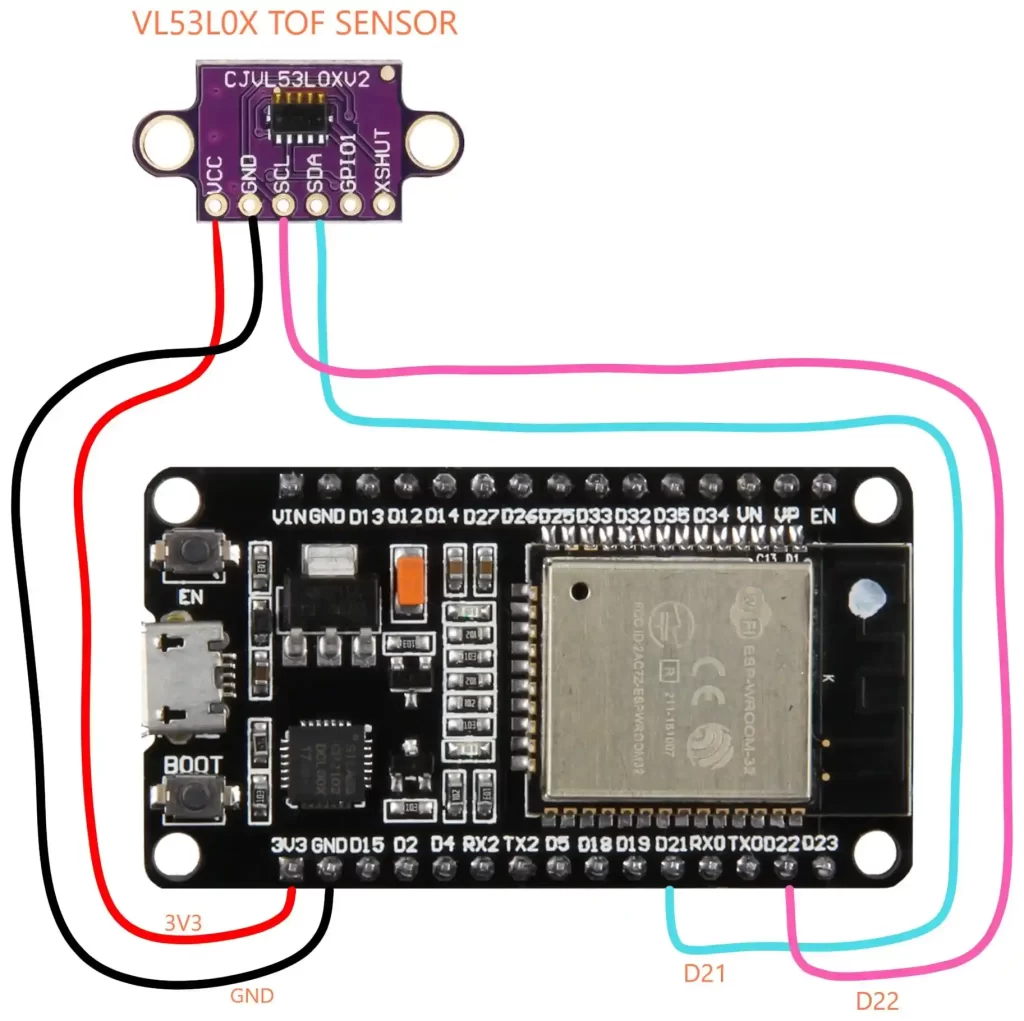
When building a mapping robot, your robot needs to understand two things: how far an obstacle is and where it is facing. The VL53L0X Time-of-Flight (ToF) sensor helps with the first part—it measures distance using light, not sound or touch. Think of it as giving your robot a tiny laser ruler.
The VL53L0X works by emitting a pulse of infrared light and then measuring how long it takes for that light to bounce back after hitting an object. Because light travels at a constant speed (about 300,000 km per second), the sensor can calculate the distance based on the time of flight of that light pulse—hence the name Time-of-Flight sensor.
We have covered this sensor in detail here
Unlike ultrasonic sensors that can get confused by soft or angled surfaces, the VL53L0X is very precise and works well indoors under various lighting conditions. It can measure distances up to about 2 meters with millimeter-level accuracy. In your ESP32 robot, it will help create a simple map of nearby obstacles, while the MPU6050 sensor will track rotation and orientation. Together, they let your robot estimate where objects are in its surroundings.
VL53L0X Pinout and Function
| Pin Name | Description | Connection |
|---|---|---|
| VIN | Power input (2.6V–5V) | Connect to 3.3V or 5V on ESP32 |
| GND | Ground | Connect to ground |
| SDA | I2C data line | Connect to ESP32 SDA pin |
| SCL | I2C clock line | Connect to ESP32 SCL pin |
| XSHUT | Shutdown control (optional) | Pull low to turn off sensor(Not connected) |
| GPIO1 | Interrupt output (optional) | Can signal when measurement is ready(Not connected) |
In this project, we’ll mainly use VIN, GND, SDA, and SCL, just like we did with the AS5600 encoder. Both sensors use the I2C communication protocol, which means they can share the same two wires and still work together. The ESP32 identifies each one by its unique I2C address.
When combined with the MPU6050, the VL53L0X lets your robot not only sense the distance to obstacles but also understand how it’s turning or moving. That’s how the robot can slowly build a simple “mental map” of its environment—a small but powerful step toward autonomous navigation in Arduino and ESP32-based robotics projects.
Understanding the MPU6050 Motion Sensor
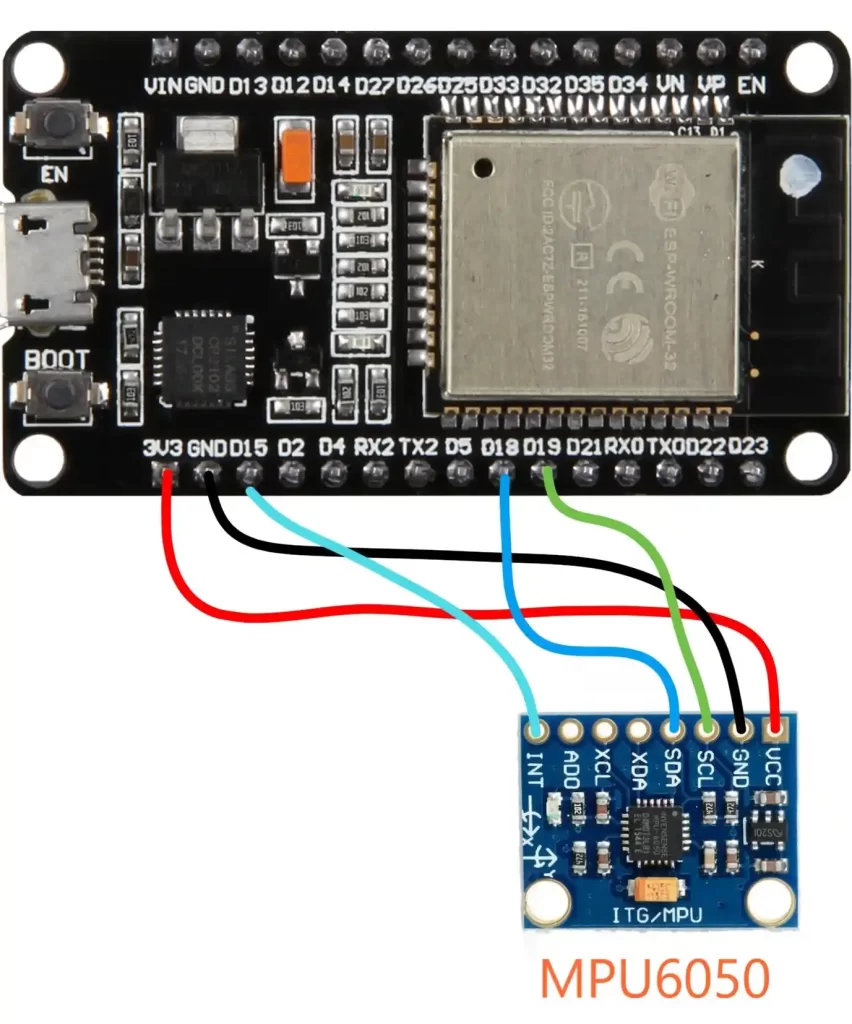
If the VL53L0X tells your robot how far things are, the MPU6050 tells it how it’s moving. This tiny but powerful sensor has a 3-axis accelerometer and a 3-axis gyroscope. Together, they allow our robot to measure both acceleration and rotation, the essential ingredients for calculating odometry and path tracking.
The accelerometer part measures acceleration in three directions (X, Y, and Z). It can sense both motion (like speeding up or slowing down) and the pull of gravity, which helps determine the robot’s tilt or angle. The gyroscope, on the other hand, measures how fast the robot is rotating around each axis. When your robot turns, the gyro detects that angular velocity, allowing you to calculate how much it has rotated. We
By combining data from both sensors using some clever math (sensor fusion algorithms like complementary filters or Kalman filters), you can track how your robot moves and turns over time. In this project, we’ll use the MPU6050 along with the VL53L0X ToF sensor.
The VL53L0X provides distance measurements, while the MPU6050 tracks the robot’s rotation, helping it “know” which direction it’s facing as it maps the area.
MPU6050 Pinout and Function
| Pin Name | Description | Connection |
|---|---|---|
| VCC | Power supply (3.3V–5V compatible) | Connect to ESP32 3.3V or 5V pin |
| GND | Ground | Connect to ground |
| SDA | I2C data line | Connect to ESP32 SDA PIN 21 |
| SCL | I2C clock line | Connect to ESP32 SCL PIN 22 |
| XDA / XCL | Auxiliary I2C pins (not needed here) | Leave unconnected |
| AD0 | I2C address select | Leave unconnected |
| INT | Interrupt output (optional) | Connect to Pin 15 on ESP32 |
Just like the other sensors we’ve used, the MPU6050 communicates via I2C protocol, so it only needs the SDA and SCL lines to talk to the ESP32. This means you can connect it on the same I2C bus as your AS5600 and VL53L0X each device has a unique address, so the ESP32 can handle them all together.
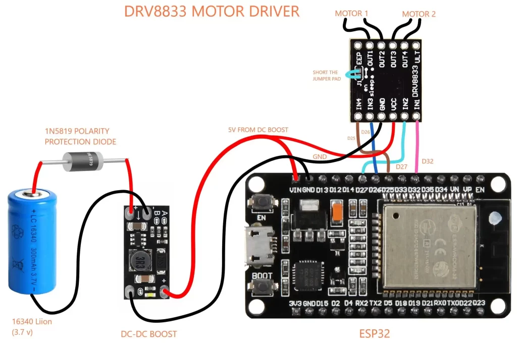
Understanding the DRV8833 Motor Driver
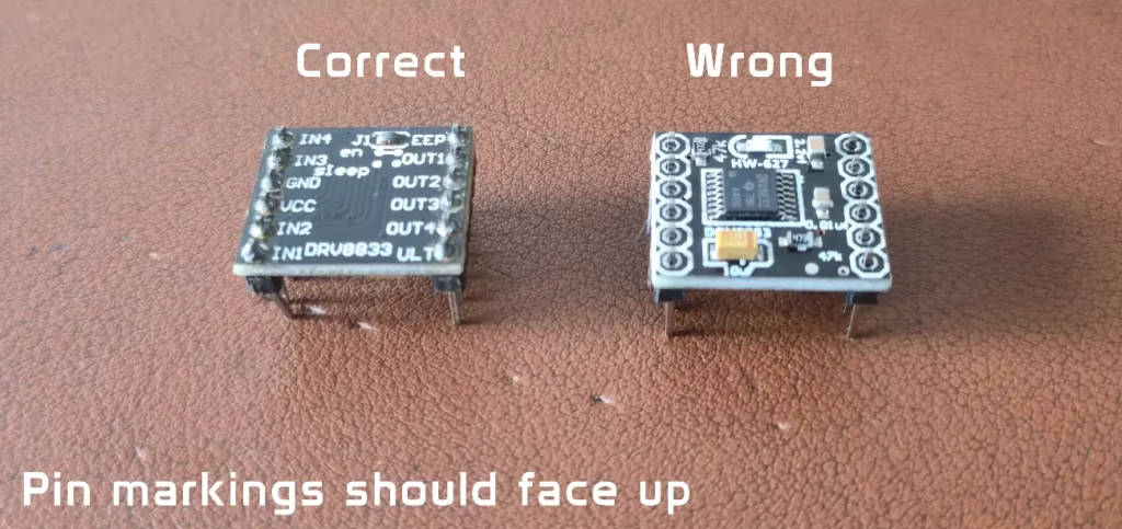
We need to solder the back jumper pad on the DRV8833 motor driver like this
The back jumper on the DRV8833 motor driver module must be soldered to enable proper power routing and motor control. Without soldering it, the driver may not function correctly or deliver full current to the motors.
Your ESP32 can think fast, but it can’t directly drive motors. Motors draw more current than the microcontroller pins can safely handle, and they need voltage and current control for direction and speed. This is where the DRV8833 motor driver steps in, it acts as the bridge between the ESP32’s logic and the robot’s motors, translating tiny control signals into powerful electrical muscle.
How It Works
The DRV8833 is a dual H-bridge motor driver, which means it can control two DC motors independently. Each “H-bridge” allows a motor to spin forward, reverse, or stop, simply by changing the direction of current flow through it.
The ESP32 sends PWM signals (Pulse Width Modulation) to the driver’s input pins. PWM works by rapidly turning power on and off by adjusting the ratio of on-time to off-time. We can control how fast the motor spins. The DRV8833 takes these logic signals and feeds the correct voltage and current to the motors.
DRV8833 Pinout and Function
| Pin Name | Description | Connection |
|---|---|---|
| VCC (Motor Power) | Supply voltage for motors (2.7V–10.8V) | Connect to boosted 5V output |
| GND | Common ground | Connect to ESP32 ground |
| AIN1, AIN2 | Control inputs for Motor A | Connect to ESP32 PWM pins |
| BIN1, BIN2 | Control inputs for Motor B | Connect to ESP32 PWM pins |
| AOUT1, AOUT2 | Outputs to Motor A | Connect to left motor terminals |
| BOUT1, BOUT2 | Outputs to Motor B | Connect to right motor terminals |
| STBY | Standby mode pin | Pull HIGH to enable driver |
| J1 Jumper (on back) | Power link for motor driver enable | Must be soldered for driver to work |
The J1 Jumper
On the back of the DRV8833 module, you’ll find a small pair of solder pads labeled J1. By default, it’s open (not connected), which means the driver won’t power up even if everything else is wired correctly.
To enable the motor driver, you must solder a small blob of solder across the J1 pads. This closes the circuit and lets power reach the DRV8833 chip. Once that’s done, your motors will respond to the ESP32’s control signals. If you skip this step, the motors will simply refuse to move—no matter how perfect your code is.
Building the Circuit: Custom PCB or Prototype Board
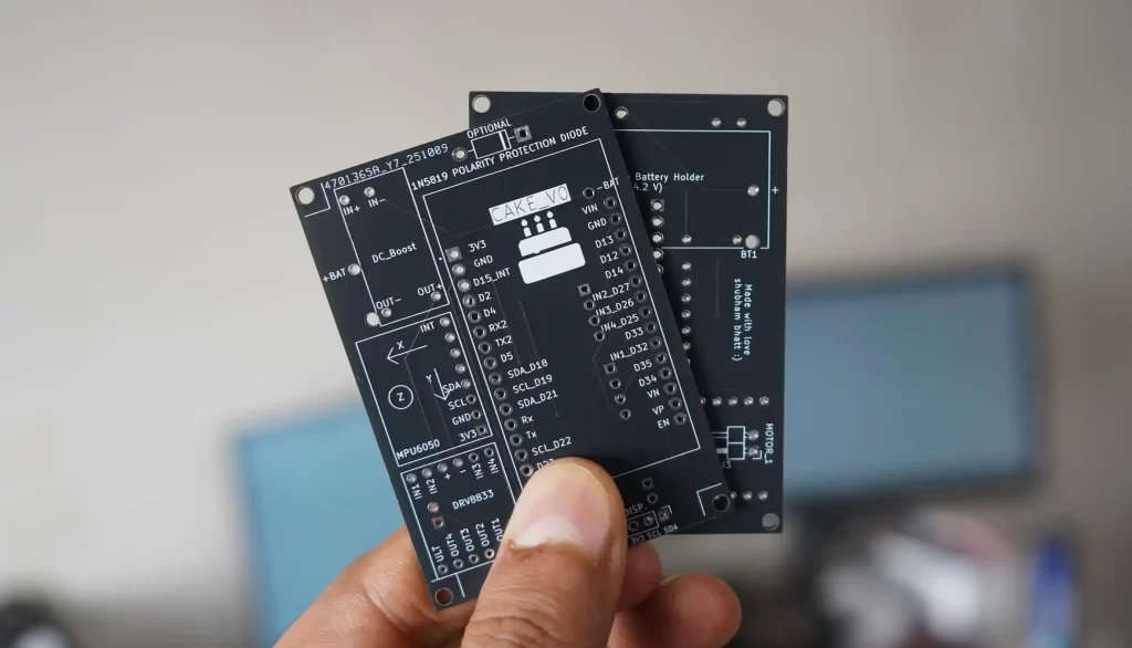
To keep things neat and reliable, I have included a custom PCB design made in KiCad. The PCB neatly holds all the components—ESP32, DRV8833 motor driver, DC-DC boost converter, sensors, and protection circuits in a 5×7 cm layout. If you’re comfortable with electronics fabrication, you can take the KiCad design files and have your own board manufactured. Most online PCB services will accept the Gerber files exported from KiCad and deliver a professional-quality board straight to your door.
A custom PCB makes life easier. You’ll get clean connections, fewer loose wires, and better mechanical stability important for a robot that vibrates and moves around. It also reduces wiring mistakes, which are easy to make when working with multiple sensors and modules.
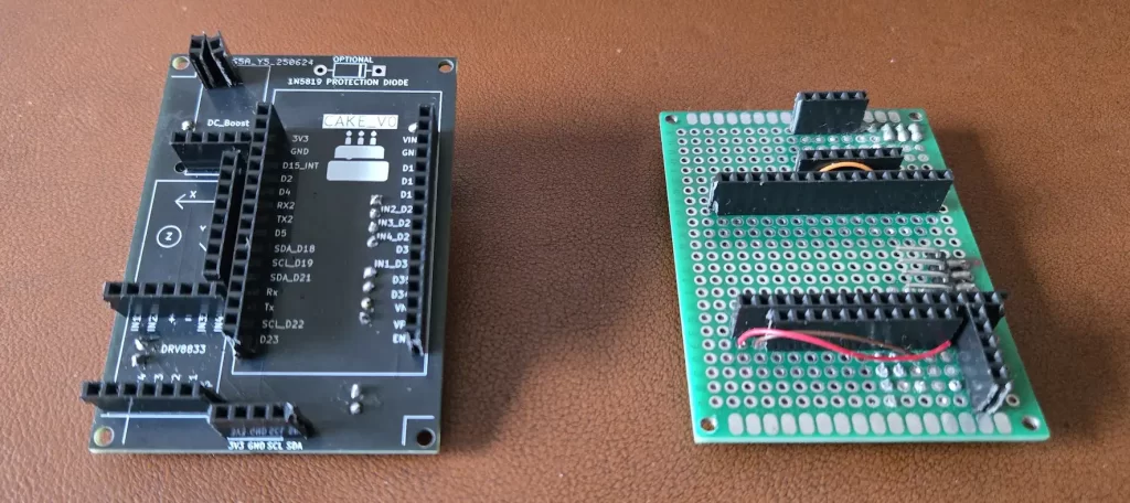
However, if manufacturing a PCB isn’t an option, don’t worry. You can still build the same circuit using a 5×7 cm prototype board (perfboard). That board is the same size as the designed PCB, so all the components will fit comfortably. You’ll just have to manually connect the pins and components using small jumper wires or solder bridges.
Every component section in this tutorial already includes wiring details. Follow those connection guides carefully while assembling your prototype board. It might take a bit more patience, but it’s a great way to learn practical wiring and circuit-building skills.
In short:
- If you can order the PCB, you’ll get a cleaner and more reliable setup.
- If you use a prototype board, you’ll get the same functionality with just a little extra soldering effort.
Both approaches will work perfectly for this project. The important part is making solid electrical connections and following the wiring diagrams shown in each section. Whether you go the manufacturing or DIY route, you’ll end up with a working robot that you can proudly call your own.
Assembling the Robot
Now, the fun part, we can start assembling the robot. Like all good things in life, our robot is 3D printed in a holy material called PLA. You think alcohol is addictive? Try 3D printing. If you don’t have access to a 3D printer, ask your school or college for help. Prepare a project report, something like an action plan, and show them how you are going to execute the project. I am sure they will help.
I looked around for an affordale 3D printing service that I could refer to people, but unfortunately, they are all expensive.
So I have also added a small 3D printing service section on this website. You may request for quote for your projects, or just DM me on Instagram for 3D printed parts for this project. You can get an instant quote for your parts and use this for negotiation with other vendors for the right price, or just email if you would like me to print for you. There is no shopping cart or checkout system; everything is done through email and UPI. Adding all these features requires some type of monthly subscription cost, which I will have to transfer to you, so to keep things cheap and affordable, this is the way 🙂
The CAD model can be downloaded from here. Download 3D model
Recommended 3D Printing Settings (for PLA)
| Setting | Parameter |
|---|---|
| Material | PLA |
| Layer Height | 0.28 mm |
| Infill | 10% |
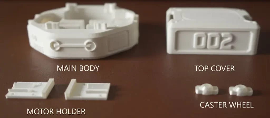
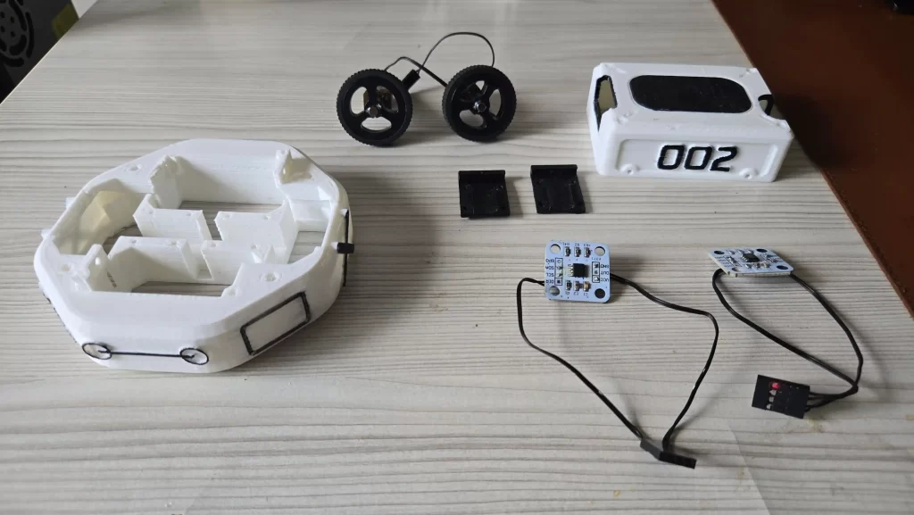
STL files can be downloaded from here. Print them according to the quantities shown below. If you do not have access to a 3D printer, there are many services available online. You can contact me through Instagram, Discord, or WhatsApp. I have a 3D printer, maybe I can help 🙂
| Item | Quantity |
|---|---|
| Main Body | 1 |
| Motor Holder | 2 |
| Caster Wheel | 2 |
| Top Cover | 1 |
Once everything is printed, we are ready to assemble our robot. Before that, please read the Electronics and wiring section. I know it’s quite long and boring, but there I have explained how to prepare the electronics, especially the DC-Boost and battery section.
Preparing Motors and Encoders
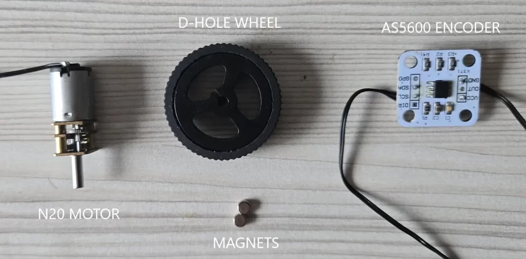
First, we will attach the motor and encoders because we need to prepare the wheels for odometry. We have to attach the magnet that comes with the encoder to the wheel. You can use hot glue and make sure the magnet is stuck straight. There is a slot for encoders in the robot chassis. It should be a press fit. Use sandpaper or a knife if there is any difficulty.
There are 2MM screw holes also given in case the module dimensions are different. Try to align the center of the wheel, magnet, and encoder chip as much as possible. Make sure there is a 1MM gap between the magnet and encoder chip; they should not rub on each other, that would be very sad :(.
Soldering PCB and Sensor Connections
Once your PCB (or prototype board) is ready, it’s time to bring it to life with solder and header pins. We’ll use a mix of female and male header pins to make the connections modular so we can remove or replace components later without desoldering anything.
The female headers go on the top side of the PCB. These will hold your main electronic modules like the ESP32, motor driver, boost converter, and sensors. Inserting the components into female headers keeps things tidy and makes troubleshooting easy if something ever needs to be swapped out.
On the bottom side of the PCB, we will solder 90-degree male header pins. These pins will connect to the motors and encoders. The angled design helps the wires exit cleanly toward the chassis, preventing them from sticking straight down and getting in the robot’s way.
When soldering, make sure the pins are straight and properly aligned before applying heat. Take your time; misaligned headers make it difficult to mount modules properly later. Also, double-check the pin labels printed on the PCB. Each module has its corresponding pin names (like VCC, GND, SDA, SCL, IN1, IN2, etc.). Following these labels is critical because reversing connections, especially power lines, can permanently damage your components.
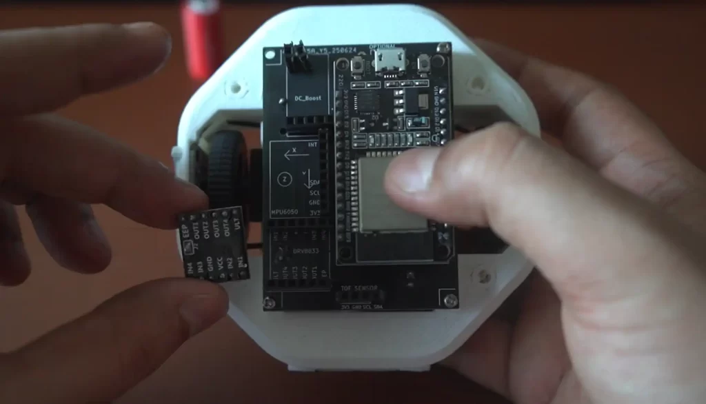
You can refer to the PCB image provided for guidance on placement and orientation. It clearly shows which side each header and module should go on.
Motor and Encoder Connection
At the edges of the PCB, you’ll see dedicated markings for motor and encoder connections. These are clearly labeled to make sure everything goes to the right wheel.
- Motor_1 and Encoder_1 correspond to the right wheel.
- Motor_2 and Encoder_2 correspond to the left wheel.
Connect the right-side motor’s wires to Motor_1 and its corresponding AS5600 encoder to Encoder_1. Do the same for the left side with Motor_2 and Encoder_2. Keeping these consistent ensures that when you write your movement code, both wheels spin in the correct direction and the encoder readings match each wheel’s motion.
Incorrect wiring can cause confusing behavior, like one wheel spinning backward while the robot thinks it’s going forward. So always confirm connections before powering up.
Mounting the PCB to the Chassis
Once all the soldering is done, mount the PCB onto your robot’s chassis using 2×10 mm screws. Make sure the board sits flat and doesn’t press against any metal parts of the chassis. With the board secured, your ESP32 robot’s electronics will be firmly attached, well-organized, and ready for testing.
Assembling the 3D Printed Chassis
Now that all the electronics are soldered and mounted on the PCB, it’s time to give your ESP32 robot its body. The chassis is completely 3D printed, designed to keep everything compact, sturdy, and easy to assemble. The design is simple but functional, ensuring that each part fits perfectly while maintaining the robot’s balance and stability.
Step 1: Mounting the Motors
Start with the main body of the chassis. It has two side slots where the DC motors will slide in. These slots are sized precisely for the N20 motor body, so the fit should be snug. Insert each motor carefully into its slot. Make sure the wheel and encoder magnets are already attached to the motor shaft before putting it in.
To hold the motors firmly in place, use the 3D printed motor holders. These parts are shaped to clamp over the motors and bolt onto the chassis. Align each holder with the holes on the main body and fasten them using small screws. Tighten them just enough to keep the motors secure, but not so tight that you bend or stress the plastic.
Step 2: Adding the Caster Wheel
Once the motors are mounted, move to the back of the robot. This is where you’ll install the 3D printed caster wheel. The caster acts as a balancing point for the robot, supporting the rear side where the battery is mounted. Since the battery is the heaviest part of the robot, placing the caster at the back ensures even weight distribution and stable movement.
Attach the caster wheel bracket to the chassis using screws. There are two slots for caster wheel, one in front and another at the back. We only need one, but if required, you may use both.
Step 3: Installing the Top Cover
With the motors and caster in place, position the PCB assembly on top of the chassis. Secure it with 2×10 mm screws through the mounting holes provided. Once fastened, the board should sit flush and stable above the motors.
Finally, place the top cover. The cover is also 3D printed and designed with small interlocking tabs that provide light resistance. This means it stays in place during normal operation but can be easily removed whenever you need to access the electronics. There are no screws for the top cover, which makes it more convenient for quick maintenance or battery swaps.
ESP32 Code Explained
Now we are ready for coding :). In this section, I will explain how the ESP32 code works. This code we will upload to our robot. We will use Arduino IDE for compiling and uploading code. I’ll explain how to install the ESP32 board support, and give step-by-step instructions for installing the libraries your project needs. Follow these steps carefully, and you should be up and running.
First, you will need to install the Arduino IDE. By default, there are no ESP32 boards on the Arduino IDE. So we will have to add them. I have explained this process here.
Download code from GitHub
Install libraries
Before we start compiling the code, we need to install libraries. Most of the libraries can be found in the Arduino IDE directly
#include <Wire.h>                    // I2C bus library (core)
#include <WiFi.h>                    // Wi-Fi support for ESP32 (board package)
#include <WiFiUdp.h>                 // UDP networking over Wi-Fi
#include <ESPmDNS.h>                 // mDNS responder for network name resolution
#include <ArduinoOTA.h>              // Over-the-air programming support
#include <Adafruit_VL53L0X.h>            // Driver wrapper for VL53L0X ToF sensor (third-party)
#include "MPU6050_6Axis_MotionApps612.h" // MPU6050 motion/ DMP helper (third-party)
#include "BR_DRV8833.h"                // Driver wrapper for DRV8833 motor driver (Bench-Robotics)
#include "WheelOdometry.h"           // Custom libray for wheel odometry (Bench-Robotics)
#include "DataParser.h" // Custom libray for reading commands sent over Wi-Fi (Bench-Robotics)WheelOdometry, BR_DRV8833 and DataParser are custom libraries written by me and are included with the code, so no need to install them.
#include "WheelOdometry.h"
#include "DataParser.h"
#include "BR_DRV8833.h"There are two common ways to add libraries: Library Manager (recommended when available) and Add .ZIP Library (for GitHub or manual ZIPs).
1. Use Library Manager (preferred for common libraries)
- In Arduino IDE, go to Sketch → Include Library → Manage Libraries…
- In the Library Manager search box, type the library name (for example
ArduinoOTA,ESPmDNS,VL53L0X). - Click the library entry and press Install.
- Repeat for each library available via Library Manager.
Which ones you’ll likely find in Library Manager:
ArduinoOTA— installable once the ESP32 package is present.ESPmDNS— usually available with ESP32 board support or as a separate library.Adafruit_VL53L0X— Several variants exist; search forAdafruit_VL53L0XMPU6050— Multiple libraries exist. The MotionApps DMP one (MPU6050_6Axis_MotionApps612) is a specific variant you may need to install manually if not present.
2. Install libraries from ZIP or GitHub (manual)
If a library is not present in Library Manager, do this:
- Download the library ZIP from its GitHub repo or the source you trust.
- In Arduino IDE, go to Sketch → Include Library → Add .ZIP Library…
- Select the downloaded ZIP. The IDE will unzip and install it into your
librariesfolder. - Restart the IDE if the library does not appear.
Once all the libraries are installed, compile the code to check the installation. If all is ok, be happy; if not, then we will try again. You ask me for help on Discord. I will update this section in detail if more people have problems. It’s already been a week, and my fingers are numb typing this article.
Change the Wi-Fi credentials and PC IP address
Before uploading the code, we will have to make some changes to the code so that it can connect to your wifi hotspot and PC
- Replace the Wi-Fi SSID and Password
- Replace remoteIP with your PC’s IP address
- Motor rotation direction
Replace with your Wifi SSID and Password; otherwise, the robot will not be able to receive messages from the PC or mobile app
#define WIFI_SSID "ground"         //Replace with your own Wi-Fi name
#define WIFI_PASSWORD "12345678"   //Repalce with your password
#define UDP_PORT 12345Replace this IP address with your PC’s local IP address. For this, we will have to use the command prompt on Windows. As long as you are on the same wifi network, this should not change very often. We need to do this so that the path visualizer software can receive the data being sent by the robot over wifi.
const char* remoteIP = "192.168.1.11"; // Add your PC IP addressHow to get the Local IP address on Windows:
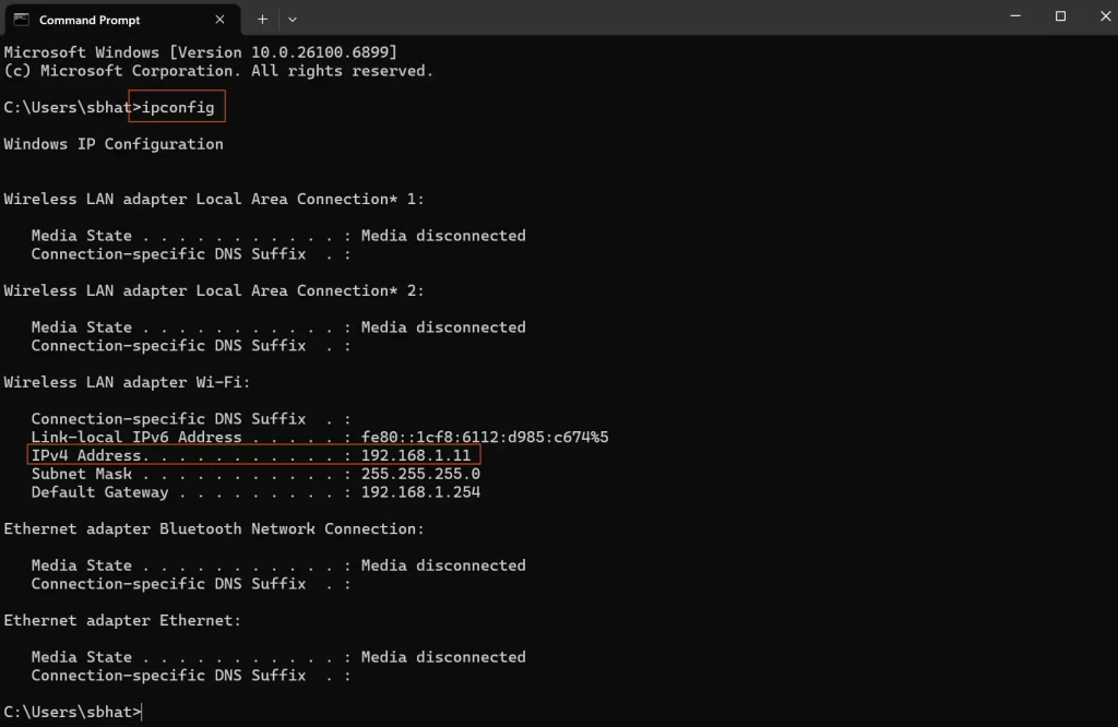
- Press
Windows + Rto open the Run dialog. - Type
cmdand hit Enter to open Command Prompt. - In the Command Prompt window, type:
ipconfig - Press Enter.
- Look for the line that says IPv4 Address under your active network adapter (usually “Wireless LAN” or “Ethernet”).
- Example:
IPv4 Address. . . . . . . . . : 192.168.1.5
- Example:
On macOS:
Sorry, I don’t have Apple, so no screenshot 🙂 Somebody please try this and verify.
- Click the Apple menu → System Settings (or System Preferences).
- Go to Network.
- Select your active connection (Wi-Fi or Ethernet).
- Your IP address will be shown on the right panel.
Correct wheel spinning direction
After wiring the robot, when you try to run the robot, there is a good chance it won’t follow the correct command. For example, for forward command, it might turn right or left, and the command might go backward. This is no big deal to fix; we will have to switch the motor power connection. We can physically do this or in software. We will do it with software because we are smart :). You will face this issue once you have installed the mobile app, which is explained in the next section. Please go through that and come back. Bring cookies 🙂
| motorA | Right Motor |
| motorB | Left Motor |
  // Change true or false to change direction of rotation of motors
  motorA.setDirectionFlip(false);
motorB.setDirectionFlip(true);For your robot to move the way you expect, both wheels must spin in the correct direction relative to each other. The direction each motor rotates determines whether the robot goes forward, backward, or spins in place. If one motor spins the opposite way, the robot will either rotate in circles or move unpredictably.
When viewed from the side, here’s how the motors should behave:
| Movement | Right Motor Rotation | Left Motor Rotation |
|---|---|---|
| Forward | Clockwise | Anticlockwise |
| Backward | Anticlockwise | Clockwise |
If your robot doesn’t move forward or backward correctly when testing, don’t worry. Simply reverse the direction of one motor in your code. For instance, to change the direction of rotation of motorA change the argument from true to false
Before:
motorA.setDirectionFlip(true);
motorB.setDirectionFlip(true);After:
motorA.setDirectionFlip(false);
motorB.setDirectionFlip(true);Alternatively, you can reverse the wiring on that motor’s terminals, but changing it in code is usually simpler and safer once everything’s soldered
Download the code from here. Upload. Get the IP address once connected to the hotspot.
Important Functions explained
The magic happens in the void loop() This is where all the little functions come together to make the robot work. Each of these functions has its own minion functions. We will not go into that much detail. The main program is quite simple and easy to read. I have added comments everywhere.
void loop() {
  ArduinoOTA.handle();  //Handels OTA updates
  process_imu();        //Reads IMU
  odom();               //Calcualtes Wheel rotation
  measure_distance();  //Tof sensor measurements
  data_to_send();      //Sends data to external devide over wifi
  udpReceiveTask();    //Receives data from external device like pc or phone
}void measure_distance() This part of the code measures the distance using the Tof sensor. This helps in obstacle avoidance and mapping. It looks small, but the real magic is done by the library we are using.
void measure_distance()
{
   uint16_t NewMeasurement;
   VL53L0X_RangingMeasurementData_t measure;
   lox.rangingTest(&measure, false); // Pass in 'true' to get debug data printout!
    if (measure.RangeStatus != 4) { // If there is no error
   // Serial.print(F("Distance: "));
    Serial.println(measure.RangeMilliMeter);
    globalDistance = measure.RangeMilliMeter;
    //Serial.println(F(" mm"));
  } else {
    Serial.println(F("Out of range"));
  }
}void odom() Helps in calculating the wheel odometry. It reads the rotation angle for each wheel and packs it in the global variable globalOdom, which we later send to the PC for further calculation. Odometry and path calculation are done on a PC. This function just reads the wheel angle.
void odom()
{

   // Update odometry for both wheels
    leftWheel.update();
    rightWheel.update();

    // Get and print odometry data
    float leftOdometry = leftWheel.getOdometry();
    float rightOdometry = rightWheel.getOdometry();

    //Serial.print("Wheel 1 Odometry (radians): ");
    //Serial.print(leftOdometry);
    //Serial.print(",");
    //Serial.println(rightOdometry);

    //String Data = String(leftOdometry)+","+String(rightOdometry);
    globalOdom = String(leftOdometry)+","+String(rightOdometry);
    //transmit_data(Data);

    delay(20); // Small delay to reduce noise

}void transmit_data(String Data) This function is called when we need to send data over wifi.
void transmit_data(String Data)
{       //String Data = "Hello";
        udp.beginPacket(remoteIP, UDP_PORT);
        udp.write((const uint8_t*)Data.c_str(), Data.length());
        udp.endPacket();
} void process_imu() Calculates the angles from the IMU sensor
void process_imu()
{
  if (!dmpReady) return;

  // Read a packet from FIFO
  if (mpu.dmpGetCurrentFIFOPacket(fifoBuffer)) {
   mpu.dmpGetQuaternion(&q, fifoBuffer);

   // Send quaternion data over UDP
   char dataBuffer[100];
   //snprintf(dataBuffer, sizeof(dataBuffer), "quat,%f,%f,%f,%f", q.w, q.x, q.y, q.z);

    udp.beginPacket(remoteIP, UDP_PORT);

    float yaw = getYaw(q);
    yaw = adjustYaw(yaw);

    globalYaw = yaw;//q.z;
    //Serial.println(q.z);
  }
}There are many more helper functions in the code. Some functions might not make sense to you, like void heading_control(). It is there but not being used. This function was responsible for keeping the robot driving in a straight line, but I found a workaround by using 100RPM motors and running them at speed 40. At this speed robot moves straight, so there is no need for this. I kept this for the future; maybe I will use higher-speed motors. When the robot is following a waypoint that time the direction is controlled by the visualiser using IMU.
There is a lot of debugging code that has been commented out. I have been working on this project for more than a year at this point, and I am scared to delete anything 🙂
Upload code to the ESP32 and get the IP address of the robot
Once everything is compiled and ready, upload the code to the ESP32. Remove the battery connection before uploading the code to the robot. Otherwise, you may damage your PC port.
Once the code has been uploaded to the robot, it’s time to connect it to Wi-Fi so that we can control it remotely. Follow these steps carefully:
- Turn on your mobile hotspot or Wi-Fi network.
The robot will automatically try to connect to the credentials defined in your code. Make sure the network name (SSID) and password match exactly; these are case-sensitive. - Keep the robot connected to your computer via USB.
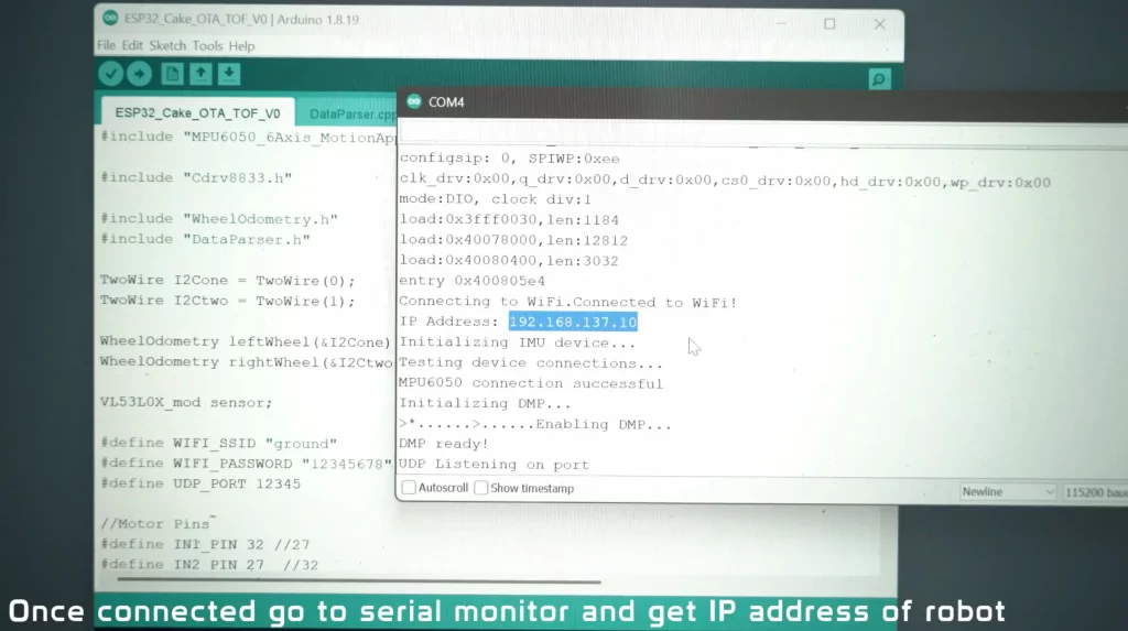
This allows you to monitor what’s happening in real time through the Arduino Serial Monitor. - Open the Serial Monitor in Arduino IDE.
You’ll find it under Tools → Serial Monitor. Set the baud rate to 115200, as that’s what the ESP32 code uses for communication. - Wait for the robot to connect.
Once the ESP32 successfully connects to Wi-Fi, you’ll see a message similar to:WiFi connected IP address: 192.168.137.10The numbers will differ on your setup, but that’s your robot’s IP address. Write it down somewhere—you’ll need it to control the robot later. - Remember, this IP address can change.
Each time the robot reconnects to the hotspot, your router may assign a different address. If the robot stops responding later, check the Serial Monitor again to see if the IP has changed.
Using OTA (Over-the-Air) Updates
CAKE also supports OTA, short for Over-the-Air programming. This is a handy feature that allows you to upload new code wirelessly as long as the robot is powered on and connected to Wi-Fi.
However, you must upload the code once using the USB cable first. This initial upload installs the OTA setup on the board. After that, the robot will appear as a network port in the Arduino IDE, and you can update it without plugging in any cables.
This makes future debugging and feature updates much faster, no need to remove the cover or hunt for the USB port. Just power it up, connect it to Wi-Fi, and program it straight through the air. This feature also draws power from the battery so you can turn it off by commenting it out to save some power.
How to control the robot
Our robot is wifi controlled using WiFi. For this to work, first, you will have to create a hotspot that our device can connect to. Robot, PC, and mobile phone must on the same wifi network. I recommend creating a hotspot on a Windows PC rather than connecting to your home wifi router.
Download the Control Centre app from GitHub (I am not rich enough for the Play Store)
Controlling the Robot with the Android App
I made the robot controllable over Wi-Fi so you can drive it from your phone.
The phone, the PC, and the robot must be on the same local network so the phone can send commands to the robot’s IP address. The app simply opens a socket connection to that IP and sends control messages (speed, forward/back/left/right).
Prepare the network
- Create a Wi-Fi hotspot that the robot can join. I recommend using a Windows PC hotspot because it usually keeps devices on one simple local network.
- On Windows: Settings → Network & internet → Mobile hotspot, choose a name and password, and turn it on.
- You could also use your phone’s hotspot or your home router, but be aware that routers sometimes isolate guest devices; if you run into trouble, the PC hotspot tends to be the simplest.
- Make sure the robot, the PC (for debugging), and your Android phone are all connected to the same hotspot. Turn off mobile data on the phone while testing to avoid routing confusion.
- Keep the robot connected and open the Arduino IDE Serial Monitor on the PC to see connection logs and to read the robot’s current IP address if needed.
Install the Android app (APK)
The app is distributed as an APK file. Android will usually block installation of apps from outside the Play Store by default, so you will need to allow it.
- Copy the APK to your phone.
- On the phone, open your file manager and tap the APK to start installation.
- If Android blocks it, follow the phone’s prompts to allow installations from that app source. On modern Android versions, that path will look like: Settings → Apps → Special app access → Install unknown apps, then enable the app (for example, your file manager or browser) you are using to install the APK. Exact wording may vary by Android version.
- Accept the installation and finish. If the phone warns you about security, remember you are installing a local control app you wrote or trust for this project. Use caution with apps from unknown sources in general.
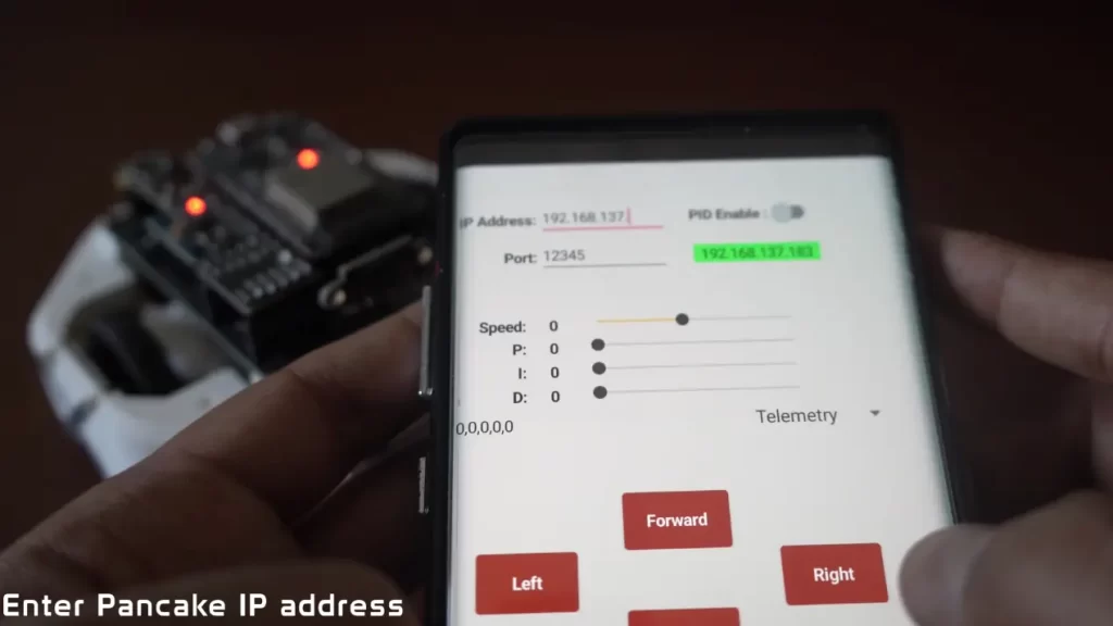
Open the app and select the project
- Launch the installed app. You may see a list of my old projects or robots.
- Choose the project named CAKE. Selecting CAKE will open the control screen with the IP/port fields and the control UI.
- In the app’s control screen, enter the robot’s IP address exactly as shown in the Serial Monitor (for example
192.168.43.27). - Enter the port by default, it’s 12345; you can change it, but update the ESP32 code also.
- Tap Connect in the app. The app should show a “connected” indicator if the robot accepts the connection.
Note: the IP is not guaranteed to stay the same each time the robot connects. If the robot won’t respond later, re-open Serial Monitor to get the new IP or set a static IP in your hotspot/router if you want permanence.
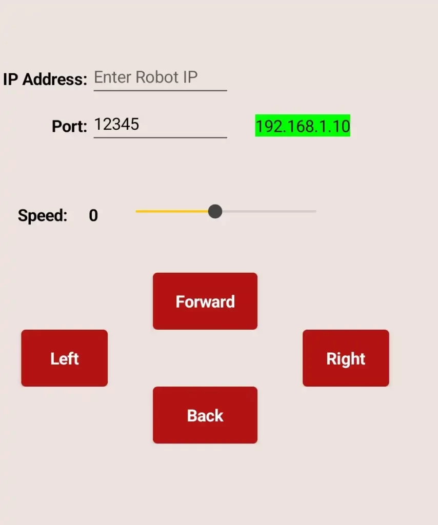
Controls and recommended settings
The app provides a speed slider and directional buttons. Here is a small table describing the controls and a recommended starting value:
| Control | What it does | Recommendation |
|---|---|---|
| Speed slider (0–100) | Scales motor PWM from stop to full speed | Start at 40 for safe testing |
| Forward button | Move the robot forward | Hold briefly, check motion |
| Backward button | Move the robot backward | Same as above |
| Left / Right buttons | Rotate or arc-turn the robot | Use short taps for heading corrections |
Use the slider to limit top speed during early tests. Running at 40 gives responsive movement without too much torque or risk of damage.
Test sequence (safe, quick)
- With everything connected, set the speed to 40.
- Press Forward for one or two seconds and observe the direction. If wheels spin the wrong way, see the motor direction section earlier for how to invert one motor in code.
- Test Backward, Left, and Right similarly.
- If the robot does not respond, check the Serial Monitor on the PC for incoming connection messages. If the app reports “cannot connect”, recheck the IP and port.
Troubleshooting tips
- If the app fails to connect but the phone is on the same Wi-Fi, confirm the robot actually has the IP you entered by checking the Serial Monitor.
- If the app connects but the robot does not move, confirm the motors are powered and the DRV8833 J1 jumper is soldered.
- If the battery is low robot will disconnect, but the light will stay on. Unfortunately, there is no battery indicator on board. I roughly get 15 Minutes of runtime. So if this happens, please switch to a new one.
This app talks to the robot over your local network without encryption, so avoid using it on untrusted public Wi-Fi.
Robot Waypoint Navigation and Mapping
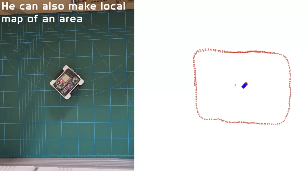
By combining IMU, encoders, and the VL53L0X Tof sensor, CAKE has the ability to track its path and make a local map of an area. We can also click on the screen to place waypoints, and the robot will follow them. All this is done using the Visualiser program, which is written in Processing (Java-based). Processing and Arduino IDE have the same interface, so it should be quite familiar.
First step, like Arduino IDE, we will install the following libraries. Go to the library manager and search for the hypermedia.net
import hypermedia.net.*;  // Import the UDP library
import java.util.ArrayList;
import java.util.concurrent.CopyOnWriteArrayList;To receive and send data to the robot, we will have to define the robot’s IP address in the code. Please replace with the Robot IP address along with the port, which is 12345 by default
String robotIP = "192.168.137.19";  // Replace with your robot's IP
int robotPort = 12345;           // Replace with your robot's listening port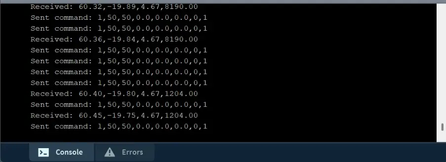
Once the robot, PC, and phone are connected to the same wifi network, run the program. If everything is working correctly, you will see some output in the console. If the robot is moving and you are not able to see anything, then probably the IP address is wrong. The IP address will change every time you turn on the robot.
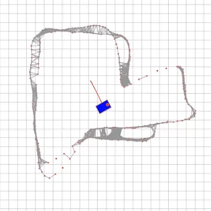
Once everything is connected properly, you should see the robot making a map and drawing its path as it moves. VL53L0X just has a single beam, so to make the map, you will have to spin the robot in its place. This is a cheap sensor, so you should see the rough outline of the obstacles. I am experimenting with better ones.
I am also experimenting with autonomous navigation using A*. Once a rough map of the area has been made user can click anywhere on the screen. If there are new obstacles in front of the robot, the robot will make a new path to avoid obstacles and try to reach its goal. This is an experimental feature not included in the current code. I am developing a new program in Python for full automation driving.
Important Functions explained
The draw() Function is the heart of the robot’s visual feedback loop. It continuously updates the canvas to reflect the robot’s movement and its interaction with predefined waypoints. Here’s what it does step by step:
- Canvas Reset: Clears the screen with a white background to prepare for a fresh frame.
- Path Rendering: Draws the robot’s traveled path in red using a series of connected vertices stored in the
pathlist. - Robot Display: Calls
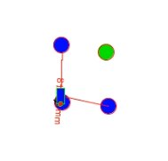
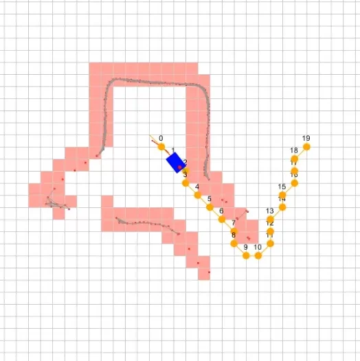
drawRobot()to render the robot’s current position and orientation. - Waypoint Visualization:
- Loops through all waypoints, drawing each as a blue circle.
- Highlights the current target waypoint in green.
- Surrounds each waypoint with a green boundary circle to indicate the proximity threshold.
- Navigation Line: Draws a green line from the robot’s current position to the active waypoint, helping visualize the direction of movement.
- Waypoint Following: Finally, it calls
follow_waypoint()to update the robot’s behavior based on its current target.
void draw() {
  // Clear the screen
  background(255);

  // Draw the robot and path
  stroke(255, 0, 0);
  noFill();
  beginShape();
  for (PVector p : path) {
    vertex(p.x, p.y);
  }
  endShape();
  drawRobot();

  // Draw all waypoints
  for (int i = 0; i < waypoints.size(); i++) {
    PVector waypoint = waypoints.get(i);

    // Highlight the current waypoint
    if (i == currentWaypointIndex) {
      fill(0, 255, 0);  // Green for the current waypoint
    } else {
      fill(0, 0, 255);  // Blue for other waypoints
    }

    // Draw the waypoint and boundary
    ellipse(waypoint.x, waypoint.y, 10, 10);  // Waypoint
    noFill();
    stroke(0, 255, 0);
    ellipse(waypoint.x, waypoint.y, waypointBoundary * 2, waypointBoundary * 2);  // Boundary
  }

  // Draw a line from the robot to the current waypoint
  if (!waypoints.isEmpty() && currentWaypointIndex < waypoints.size()) {
    PVector currentWaypoint = waypoints.get(currentWaypointIndex);
    stroke(0, 255, 0);
    line(x, y, currentWaypoint.x, currentWaypoint.y);
  }

  // Follow the current waypoint
  follow_waypoint();
}The receive() The function is responsible for interpreting incoming data from the robot’s sensors—specifically, the rotation angles of its left and right wheels. This data is crucial for calculating the robot’s position and orientation using odometry. Here’s how it works:
- Data Conversion: The function starts by converting the incoming byte array into a readable string and trims any extra whitespace.
- Parsing Angles: It splits the string by commas to extract the left and right wheel angles. These angles represent how far each wheel has rotated.
- Validation: It checks that exactly two values are received and ensures they are valid numbers (not NaN).
- Delta Calculation:
- Computes the change in angle since the last update for both wheels.
- Converts these angle changes into linear distances using the wheel radius.
- Odometry Update:
- Calculates the robot’s change in orientation (
dTheta) based on the difference in wheel movement. - Computes the change in position (
dX,dY) using trigonometry. - Updates the robot’s global position (
x,y) and orientation (theta).
- Calculates the robot’s change in orientation (
- Path Tracking: Adds the new position to the
pathlist for visualization. If the path grows too long, it trims older entries to save memory. - Debugging Info: Throughout the process, it prints useful logs to help monitor the robot’s state and catch any errors.
This function is the backbone of real-time localization, allowing the robot to understand where it is and how it’s moving—pure math magic in motion!
void receive(byte[] data) {

 String inString = new String(data).trim();  // Convert the byte array to a string and trim it
  println("Received: " + inString);  // Print the received string for debugging


  if (inString != null) {
    inString = trim(inString);  // Remove any whitespace characters
    println("Received: " + inString);  // Print the received string for debugging

    String[] angles = split(inString, ',');  // Split the data by comma

    // Check if we received exactly two values
    if (angles.length == 2) {
      try {
        // Parse the angles and handle potential errors
        float angleL = float(angles[0])*-1;  // Left wheel angle in radians
        float angleR = float(angles[1]);  // Right wheel angle in radians
        //float heading = float(angles[2]);

        // Convert heading from -180 to 180 range to 0 to 360 range
      //  if (heading < 0)
    //  {
    //    heading += 360;
   //   }

        // Check for NaN values
        if (!Float.isNaN(angleL) && !Float.isNaN(angleR)) {
          // Calculate the difference from the previous angles (these are absolute values)
          float deltaAngleL = angleL - prevAngleL;
          float deltaAngleR = angleR - prevAngleR;

          // Update previous angles for the next iteration
          prevAngleL = angleL;
          prevAngleR = angleR;

          // Compute the distance each wheel has traveled
          float dL =   deltaAngleL * wheelRadius;  // Distance covered by left wheel (negated)
          float dR = deltaAngleR * wheelRadius;  // Distance covered by right wheel

          // Compute the robot's linear and angular displacement
          float dTheta = (dR - dL) / wheelBase;  // Change in orientation (radians)

          //theta = radians(heading);
          // Update only if there is a significant change
          if (abs(dTheta) > 0.0001 || abs(dL + dR) > 0.0001) {
            float dX = ((dL + dR) / 2) * cos(theta + dTheta / 2);  // Change in X
            float dY = ((dL + dR) / 2) * sin(theta + dTheta / 2);  // Change in Y

            // Update robot's position and orientation
            x += dX * scalingFactor;  // Apply scaling for visualization
            y += dY * scalingFactor;  // Apply scaling for visualization
            theta += dTheta/2;


            // Add the new position to the path list
            path.add(new PVector(x, y));
            if (path.size() > 1000) {  // Limit the path length to avoid memory issues
              path.remove(0);
            }
          }

        } else {
          println("Invalid data: NaN values received.");
        }
      } catch (NumberFormatException e) {
        println("Error parsing angles: " + e.getMessage());
      }
    } else {
      println("Invalid input: Expected two values separated by a comma.");
    }

    // Print the robot's position and orientation for debugging
    println("X: " + x + " Y: " + y + " Theta: " + theta);
  }
}The follow_waypoint() The function is the brain behind your robot’s ability to autonomously navigate through a series of waypoints. It continuously checks the robot’s position and orientation, then decides whether to move forward, rotate, or stop. Here’s how it works:
- Waypoint Check: First, it ensures there are waypoints to follow and that the robot hasn’t already reached the final one. If all waypoints are completed, it sends a stop command and exits.
- Target Acquisition: Retrieves the current target waypoint and calculates the angle between the robot’s position and the waypoint.
- Orientation Adjustment:
- Computes the difference between the robot’s current heading (
theta) and the target angle. - Normalizes this angle to ensure smooth rotation decisions.
- Computes the difference between the robot’s current heading (
- Proximity Detection: Measures the distance to the waypoint. If the robot is close enough (within
waypointBoundary), it stops and advances to the next waypoint. - Heading Correction:
- If the robot isn’t facing the waypoint within a defined tolerance (
angleTolerance), it rotates left or right to align itself.
- If the robot isn’t facing the waypoint within a defined tolerance (
- Forward Motion: Once aligned, the robot moves forward toward the waypoint.
This function enables smooth and intelligent waypoint tracking, allowing the robot to navigate complex paths with minimal human intervention. It’s a beautiful blend of geometry, control logic, and real-time decision-making.
void follow_waypoint() {
  // Check if there are waypoints and the current index is valid
  if (waypoints.isEmpty() || currentWaypointIndex >= waypoints.size()) {
    // Stop the robot if there are no waypoints or we've reached the last waypoint
    send_command('s', 0, 0, 0, 0, 0, 0);
    println("All waypoints reached.");
    return;
  }

  // Get the current waypoint
  PVector currentWaypoint = waypoints.get(currentWaypointIndex);

  // Calculate the angle to the waypoint
  float deltaX = currentWaypoint.x - x;
  float deltaY = currentWaypoint.y - y;
  float targetAngle = atan2(deltaY, deltaX);

  // Calculate the angle difference
  float angleDifference = targetAngle - theta;

  // Normalize the angle to the range [-PI, PI]
  angleDifference = (angleDifference + PI) % TWO_PI - PI;

  // Check if the robot is within the waypoint boundary
  float distanceToWaypoint = dist(x, y, currentWaypoint.x, currentWaypoint.y);
  if (distanceToWaypoint < waypointBoundary) {
    // Stop the robot and move to the next waypoint
    send_command('s', 0, 0, 0, 0, 0, 0);
    println("Reached waypoint: " + currentWaypointIndex);
    currentWaypointIndex++;
    return;
  }

  // Check if the robot is facing the waypoint within the tolerance range
  if (abs(angleDifference) > angleTolerance) {
    // Turn towards the waypoint
    if (angleDifference > 0) {
      send_command('l', moveSpeed, 0, 0, 0, 0, 1); // Rotate right
    } else {
      send_command('r', moveSpeed, 0, 0, 0, 0, 1); // Rotate left
    }
  } else {
    // Move towards the waypoint
    send_command('f', moveSpeed, 0, 0, 0, 0, 1);
  }
}