VL53L0X Time of Flight Distance Sensor ESP-32 Guide
The VL53L0X is a small and smart sensor made by STMicroelectronics. It can measure the distance to an object using a beam of invisible light. Unlike regular sensors that guess distance by how bright or loud something is, this actually measures how long light takes to travel to the object and back. Unlike regular infrared distance sensors, it uses a laser-based method to measure how far an object is. This is known as Time-of-Flight (ToF). In this article, we will cover the technical details of VL53L0X and also make a small project using ESP32.
1. What’s Inside the VL53L0X?
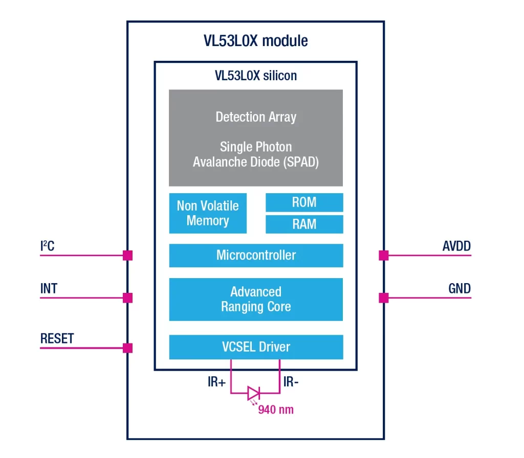
Even though it’s tiny, the VL53L0X is packed with powerful components that work together to measure distance. Don’t worry if you are having difficulty understanding the technical terms. You still will be able to use the sensor, but it is always good to know how things are working under the hood.
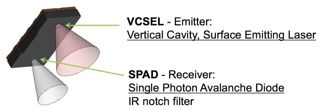
1.1 VCSEL (Vertical-Cavity Surface-Emitting Laser) – The Tiny Laser
This is the laser source. A laser diode made of special materials (like Gallium Arsenide). Emits IR light at 940 nm wavelength. It’s like a tiny LED with more focus and precision. Think of VCSEL like a flashlight that blinks really fast, but it shines invisible infrared light.
- It sends short pulses of light (like a camera flash, but faster and invisible).
- It uses very little power.
- It’s safe for the eyes.
1.2 SPAD (Single Photon Avalanche Diode) – The Photon Catcher
Tiny light sensors that act like photon tripwires. They’re built with special circuits to handle extremely fast and tiny signals.SPADs are like super-sensitive cameras that can detect even a single particle of light (photon). They work by counting individual photons from the reflected pulse — essentially detecting the first light particles to come back.
- They catch the returning light.
- If even one photon comes back, they generate a pulse.
- They work in a special mode where one photon is enough to trigger a signal (like a mousetrap).
1.3 TDC (Time-to-Digital Converter) – The Time Counter
This is the digital control part. It manages communication, timing, power control, and more. Once light is sent out and comes back, the TDC measures how long that round trip took.
- It’s like a stopwatch built into the chip.
- Since light is super fast, this stopwatch has to be extremely accurate, measuring time in nanoseconds.
1.4 AFE (Analog Front End) – The Signal Cleaner
The AFE handles the raw signals from the SPADs. It removes noise and makes the signal clean enough for the timer to use. Think of it like cleaning up a noisy audio recording so it’s easier to understand.
1.5 DSP & Microcontroller – The Brain
The sensor has a small processor running special software (called FlightSense).
- It decides when to take measurements.
- It filters and averages the results.
- It talks to your microcontroller (like Arduino or ESP32) using I2C.
2. How Time-of-Flight Measurement Works
Here’s a simple way to understand Time-of-Flight:
Imagine you’re standing in a cave. You shout, “HELLO!” and count how long it takes to hear the echo. If it takes 1 second, and sound travels 343 meters per second, then the cave wall is about 171.5 meters away (since the sound traveled there and back).
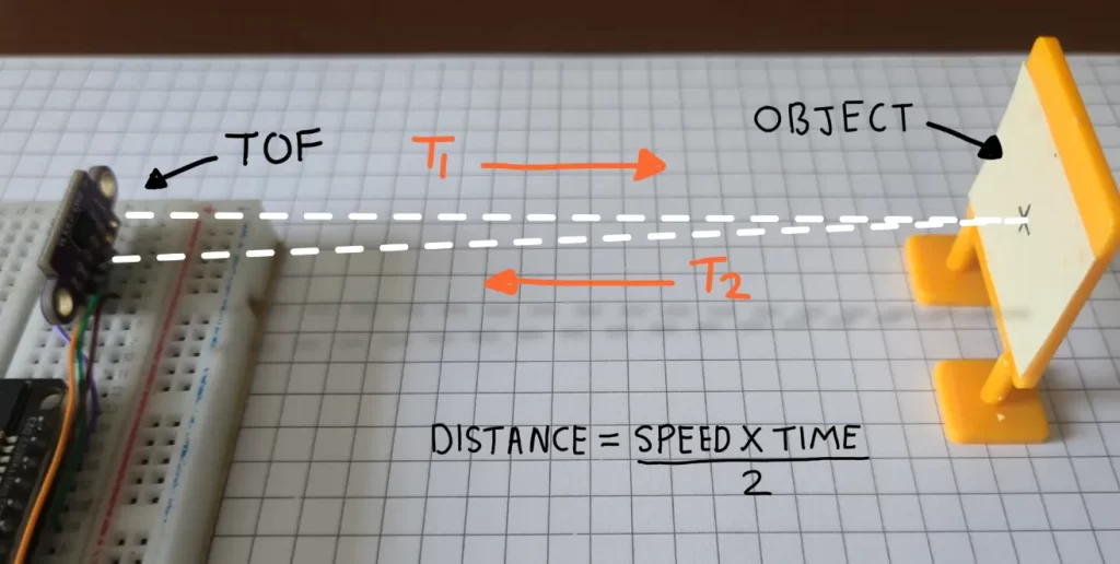
The VL53L0X does something similar, but instead of sound, it uses light.
- VCSEL sends out an IR light pulse.
- The pulse hits an object and reflects back.
- SPAD detects the return.
- TDC measures the time between send and receive.
- Distance = (Speed of Light × Time) / 2
Since light is so fast, this all happens in less than a millionth of a second!
Signal Processing Once light is detected, the chip does some smart processing:
- Histogram – Sorts all photon detections by time to find the most likely distance.
- Noise Filtering – Removes random noise (like false triggers).
- Crosstalk Compensation – Cancels out reflections from nearby parts (like the sensor’s own cover).
- Averaging – Combines multiple readings to get a clean, stable number.
- Result Register – Stores the final distance value for the microcontroller to read.
All this is done internally by the chip. For our use we don’t have to worry about all of this. The code we will use will handle all of this gives us the distance.
3. Electrical Characteristics of VL3L0X TOF
- Operating Voltage It works with power between 1.6V to 3.5V, usually set to 2.8V mode for stability.
- Communication Protocol The sensor communicates via I²C, a common two-wire protocol used in microcontrollers and embedded systems. This allows easy integration with electronics like Arduino, ESP32 or Raspberry Pi.
- Built-in Control Interface. It has an onboard Photonic Abstraction Layer (PAL) that helps convert electrical signals into meaningful distance readings, abstracting the complexities of photon detection.
| Feature | Value / Range | Meaning |
|---|---|---|
| Operating Voltage | 2.8V (3.3–5V OK) | Works with most boards like Arduino |
| Communication | I2C (up to 400 kHz) | Talks using 2 wires: SDA and SCL |
| Current Consumption | 20–40 mA (active) | Only when measuring |
| Standby Power | Few µA | Very low when idle |
| Distance Range | 30 mm to 2000 mm | From 3 cm up to 2 meters |
| Resolution | ~1 mm | Measures with millimeter precision |
4. VL53L0X Breakout Boards
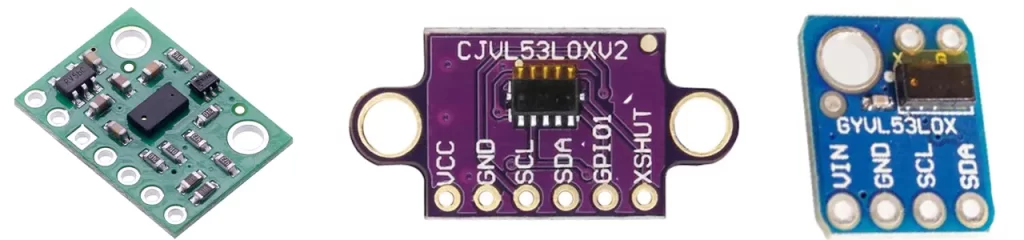
If you Google VL53L0X Time-of-Flight distance sensor, you will probably notice that the same sensor can come on different-looking boards. Don’t be confused, they are all the same sensor but with different layouts or shapes.
VL53L0X modules are sold by different vendors. While the core sensor chip VL53L0X is exactly the same, each board may have:
- Different shapes or colors (green, purple, blue)
- Different layouts of the pins
- Extra onboard components like voltage regulators or filters
Whether it’s a green, blue, or purple breakout board:
- All provide the same primary pins: VIN/VCC, GND, SDA, SCL for I²C communication
- Some include extra pins like XSHUT (shutdown control) or GPIO1 (interrupt output)
- They may support different voltage levels or have better mounting options
For this project, we’ll be using the middle board — the one with the purple layout.
| Pin | Function |
|---|---|
| VCC | Power input (2.8–5V) |
| GND | Ground (0V) |
| SDA | I2C Data line |
| SCL | I2C Clock line |
| XSHUT | Shutdown pin (pull LOW to turn off) |
| GPIO1 | Optional interrupt pin |
5. Programming VL53L0X with ESP32
Using VL53L0X is really easy; there are tons of projects there from which you can learn, but it is always good to start from the basics to build a solid foundation. So will build a simple project using ESP32 that will read the distance from the sensor using I2C pins and give the output. Don’t worry, you won’t have to do any complicated calculations or coding. Everything is done by the ESP32, and the library will be used.
5.1 ESP32 and VL53L0X I2C connection
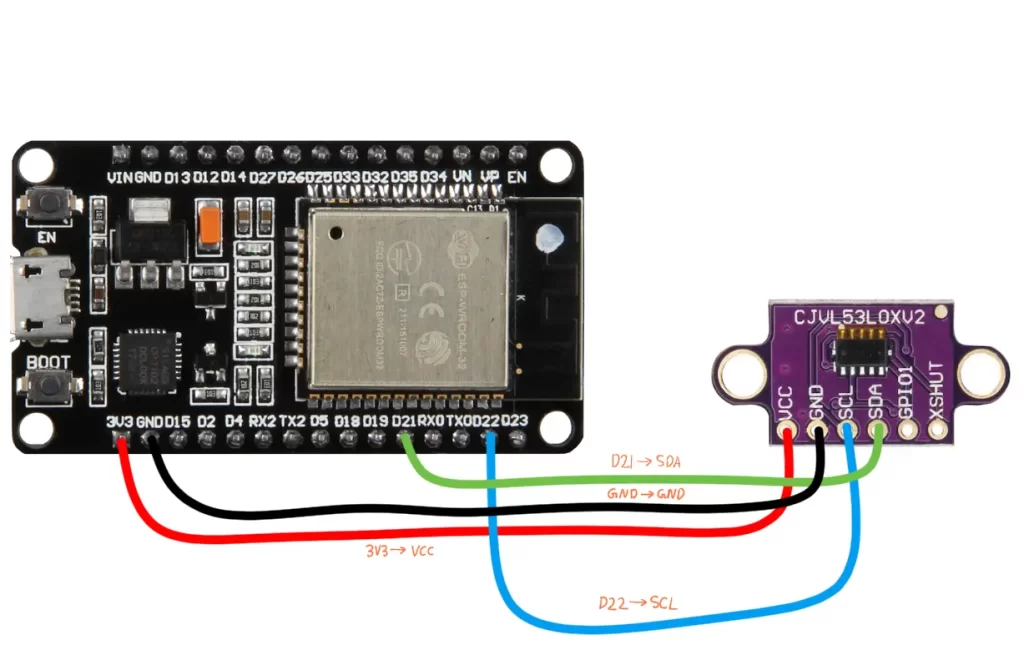
| VL53L0X Pin | ESP32 Pin | Purpose |
|---|---|---|
| VIN / VCC | 3.3V | Power the sensor (use 3.3V to avoid overvoltage) |
| GND | GND | Common ground connection |
| SDA | GPIO 21 | I²C Data line |
| SCL | GPIO 22 | I²C Clock line |
| XSHUT (optional) | Not connected / any GPIO | Shutdown control if needed |
| GPIO1 (optional) | Not connected / any GPIO | Interrupt output if needed |
5.2 Installing the library
There are many different libraries available online. They may differ in keywords or function names, so don’t be confused, you can use any library, the wiring will remain the same for all, only the code structure will change.
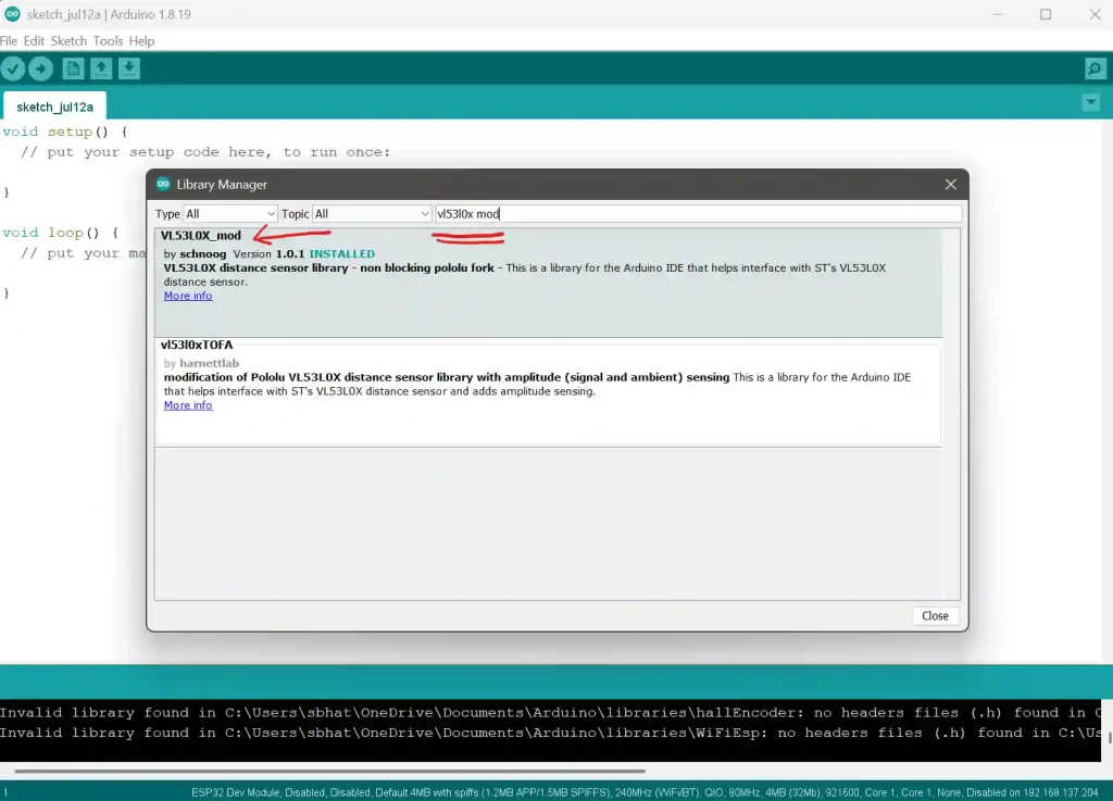
We’ll use the VL53L0X_mod library in the Arduino IDE. To install it:
- Open Arduino IDE.
- Go to Sketch > Include Library > Manage Libraries…
- In the Library Manager, type
VL53L0X_modinto the search bar. - Look for VL53L0X_mod.
- Click Install.
5.3 Code
We will learn to use this sensor by doing a small project. We will build a project that measures how far away an object is using VL53L0X. The will sensor sends out light and calculates how long it takes to bounce back, and the ESP32 will calculate the distance. Copy the code below
#include <Wire.h>
#include <VL53L0X_mod.h>

VL53L0X sensor;

void setup() {
  Serial.begin(115200);
  Wire.begin();  // use default SDA (21), SCL (22)
  sensor.init();
  sensor.setTimeout(500);
}

void loop() {
  int distance = sensor.readRangeSingleMillimeters();
  Serial.print("Distance: ");
  Serial.print(distance);
  Serial.println(" mm");
  delay(200);
}
Copy the code above, paste it into the Arduino IDE, and upload. Once uploaded, open the serial monitor on the Arduino and set the baud rate to 115200 to see the output from the ESP32.
#include <Wire.h>
#include <VL53L0X_mod.h>Wire.h: This handles communication using I²C protocol — a way for your ESP32 to talk to the VL53L0X sensor.
VL53L0X_mod.h: This is the special library that knows how to speak to the sensor, take measurements, and handle its settings.
void setup() {
Serial.begin(115200);
Wire.begin();
sensor.init();
sensor.setTimeout(500);
}This part runs once when your ESP32 boots up.
Serial.begin(115200): Starts communication with your computer so you can see results in the Serial Monitor.Wire.begin(): Starts I²C communication. By default, GPIO 21 is SDA (data) and GPIO 22 is SCL (clock).sensor.init(): Tells the VL53L0X sensor to get ready — like turning it on and loading its settings.sensor.setTimeout(500): If it takes more than 500 milliseconds to get a reading, the system will give up and move on. This prevents it from getting stuck.
void loop() {
int distance = sensor.readRangeSingleMillimeters();
Serial.print("Distance: ");
Serial.print(distance);
Serial.println(" mm");
delay(200);
}This part repeats forever, taking distance measurements every 200 milliseconds.
sensor.readRangeSingleMillimeters(): Asks the sensor to send out a laser pulse, catch the bounce, and calculate how far the object is, giving the result in millimeters.- The
Serial.printLines send the result to your computer, like: Distance: 378 mm delay(200): Waits 200 ms before repeating. You can adjust this to speed up or slow down the measurement rate.
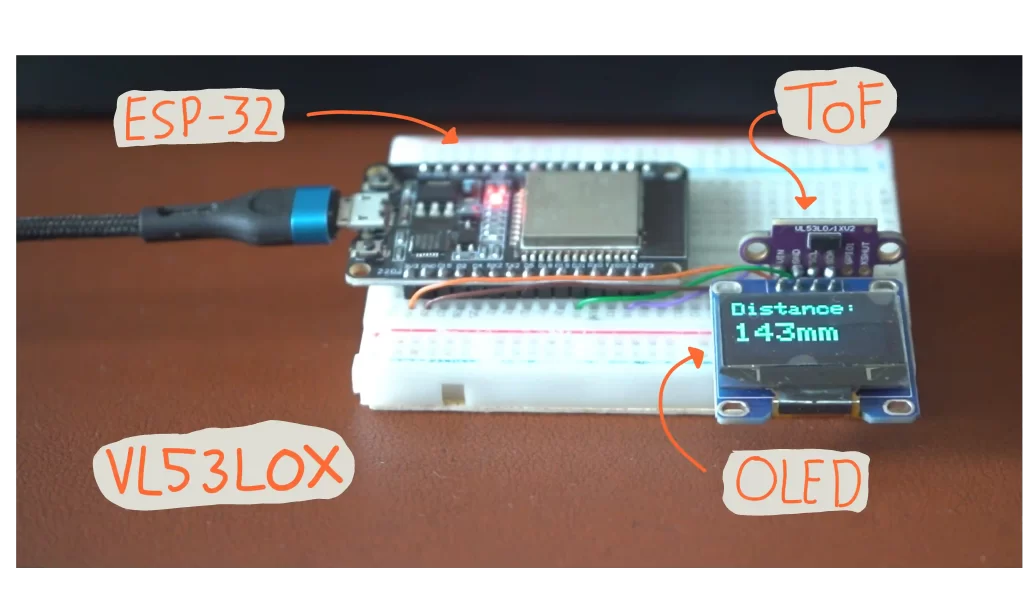
6. How To Use VL53L0X TOF Sensor with ESP32 and OLED
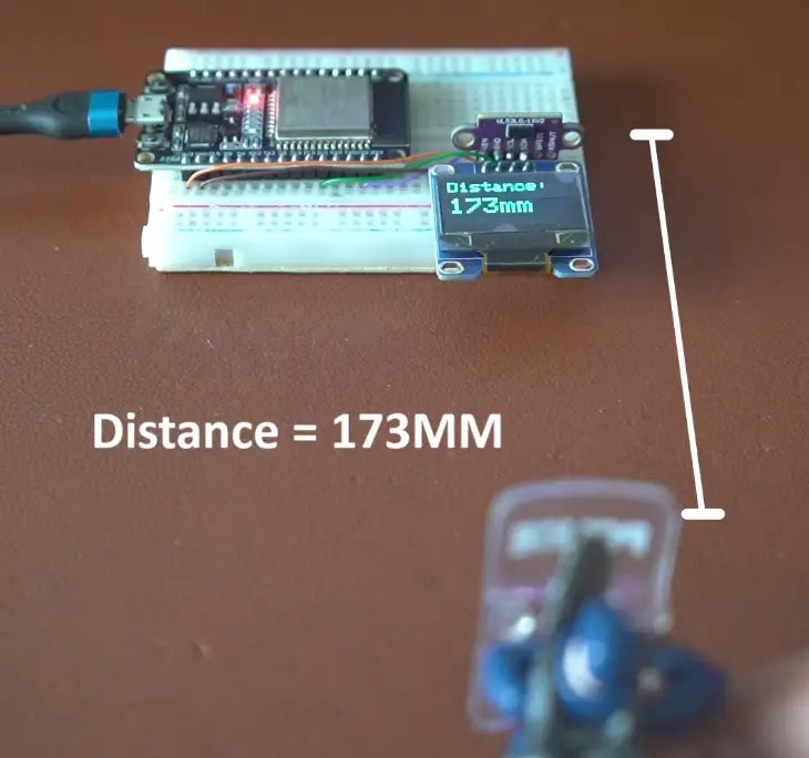
Now that we have learnt how to use VL53L0X TOF sensor with ESP32 we will add a OLED display to print the readings on it. Many projects use OLED display they make everything look cool. Both OLED and TOF sensor work with I2C so the connection is same. This was one of the reason I added this part in the article. How to use TOF along with other I2C devices.
6.1 Install OLED library
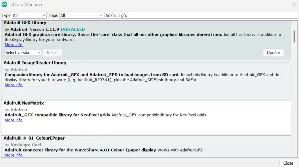
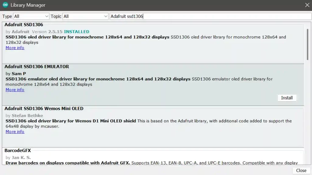
We need to install Adafruit GFX and Adafruit SSD1306 libraries in Arduino IDE to use the OLED display.
- Open Arduino IDE.
- Go to Sketch > Include Library > Manage Libraries…
- In the Library Manager, search Adafruit GFX and Adafruit SSD1306 into the search bar.
- Install both of them.
6.2 OLED and ESP32 connection
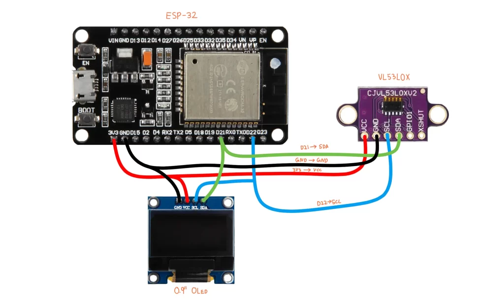
I don’t know what to say here just make the connections like this :). OLED and TOF sensor both will connect to same pins D22 and D21 because thy both use the I2C protocol.
We will use 0.9″ OLED (128×64) this is really common display for these types of projects.
| OLED Pin | ESP32 Pin | Purpose |
|---|---|---|
| VCC | 3.3V | Powers the OLED display |
| GND | GND | Ground connection |
| SDA | GPIO 21 | I2C Data line (communication) |
| SCL | GPIO 22 | I2C Clock line (timing signals) |
| RES / RST | Not used / any GPIO (optional) | Resets display—often not connected if using -1 in code |
6.3 ESP32 Code for displaying TOF values on OLED
This is the code for using VL53L0X TOF with ESP32 and display the reading on the OLED display. Let me be honest it is really simple. It might look lot of lines but nothing to worry about I am here. We will go line by line. In short, we will initialize all the libraries then politely ask the TOF sensor for the distance. Then we will ask OLED display (politely) to display the reading.
#include <Wire.h>
#include <VL53L0X_mod.h>
#include <Adafruit_GFX.h>
#include <Adafruit_SSD1306.h>
// OLED display settings
#define SCREEN_WIDTH 128
#define SCREEN_HEIGHT 64
#define OLED_RESET -1 // Use -1 if reset pin is not connected
Adafruit_SSD1306 display(SCREEN_WIDTH, SCREEN_HEIGHT, &Wire, OLED_RESET);
// TOF sensor object
VL53L0X_mod sensor;
// Calibration offset
int offset = 0;
void setup()
{
Serial.begin(115200);
Wire.begin(); // Initialize I2C
// Initialize OLED
if (!display.begin(SSD1306_SWITCHCAPVCC, 0x3C)) { // 0x3C is the OLED I2C address
Serial.println(F("SSD1306 allocation failed"));
while (true); // Infinite loop if OLED fails
}
display.clearDisplay();
display.setTextSize(1);
display.setTextColor(SSD1306_WHITE);
display.setCursor(0, 0);
display.println("VL53L0X Starting...");
display.display();
delay(1000);
// Initialize TOF Sensor
sensor.setTimeout(500);
if (!sensor.init())
{
Serial.println("Failed to detect and initialize sensor!");
display.clearDisplay();
display.setCursor(0, 0);
display.println("Sensor init FAIL!");
display.display();
while (1);
}
sensor.startContinuous(); // Start continuous mode
}
void loop()
{
int distance = sensor.readRangeContinuousMillimeters();
distance = distance - offset;
// Print to Serial Monitor
//Serial.print("Distance (mm): ");
Serial.print(distance);
if (sensor.timeoutOccurred()) {
Serial.print(" TIMEOUT");
}
Serial.println();
// Print to OLED
display.clearDisplay();
display.setTextSize(2);
display.setCursor(0, 0);
display.println("Distance:");
display.setTextSize(3);
display.setCursor(0, 25);
display.print(distance);
display.print("mm");
display.display();
delay(100); // small delay to reduce flickering
}Let me explain how code is working.
#define SCREEN_WIDTH 128
#define SCREEN_HEIGHT 64
#define OLED_RESET -1
Adafruit_SSD1306 display(SCREEN_WIDTH, SCREEN_HEIGHT, &Wire, OLED_RESET);
VL53L0X_mod sensor;
int offset = 0;- Defines the screen size in pixels.
- OLED_RESET is set to -1 because you’re not using the reset pin.
- Then it creates an OLED object named display using these settings.
Serial.begin(115200);
Wire.begin(); // Start I2C- Starts communication with your computer via USB (so Serial Monitor can show data).
- Starts I2C communication to talk to OLED and VL53L0X.
if (!display.begin(SSD1306_SWITCHCAPVCC, 0x3C)) {
  Serial.println(F("SSD1306 allocation failed"));
  while (true); // Lock up if OLED fails
}display.begin(...)tries to start your OLED screen at I2C address0x3C.- If it fails, print error and stop the program.
display.clearDisplay();
display.setTextSize(1);
display.setTextColor(SSD1306_WHITE);
display.setCursor(0, 0);
display.println("VL53L0X Starting...");
display.display();
delay(1000);- Cleans the screen.
- Sets text size, color, and position.
- Prints welcome message.
- Shows it with
display.display()and waits 1 second.
sensor.setTimeout(500);
if (!sensor.init()) {
  Serial.println("Failed to detect and initialize sensor!");
  ...
}
sensor.startContinuous();- If the sensor takes longer than 500 ms to reply, it’ll time out.
sensor.init()starts up the sensor. If it fails, print error and stop.sensor.startContinuous()starts taking distance readings nonstop.
int distance = sensor.readRangeContinuousMillimeters();
distance = distance - offset;
Serial.print(distance);
if (sensor.timeoutOccurred()) {
  Serial.print(" TIMEOUT");
}
Serial.println();- Reads the current distance in millimeters.
- Subtracts offset (if you had one).
- Shows the measured distance in your Arduino IDE.
- If sensor took too long, prints “TIMEOUT”.
display.clearDisplay();
display.setTextSize(2);
display.setCursor(0, 0);
display.println("Distance:");
display.setTextSize(3);
display.setCursor(0, 25);
display.print(distance);
display.print("mm");
display.display();
delay(100);- Clears screen and writes “Distance:” followed by the value in mm.
- Waits 100 ms before repeating the loop.
- Prevents flickering on OLED and gives smoother experience.
7. Final Thoughts
Thanks to breakout boards and libraries VL53L0X TOF is easy to use. Still, understanding how it works under the hood will help you design better and smarter projects. Whether you’re building a robot, a gesture detector, or a rangefinder, this sensor can help you do all of that. This article was just a introduction to the sensor in future I have lots of projects planned to use this.