Drawing on ESP32 OLED Screen
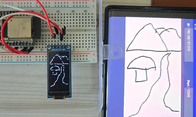
I tuned the cheap OLED into an interactive display. You can draw on the 0.9″ and 1.3″ OLED screen like an IPAD. Do you know who needs it? I made it for myself. I use OLED in most of my projects, and designing the UI for that is not fun. You have to upload the code every time you make a minor change. So I made this just by drawing directly on the screen to see how everything looks. This article is still being updated. I am adding a more detailed explanation, which may take 2 days.
1. Supplies
| Component | Quantity |
|---|---|
| ESP32 Dev Board | 1 |
| 1.3″ SH1107 OLED Display or SSD1306 0.9″ OLED | 1 |
| Jumper wires | few |
| Breadboard | 1 |
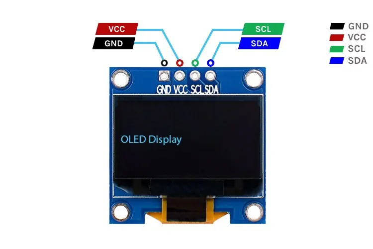
2. Wiring Diagram
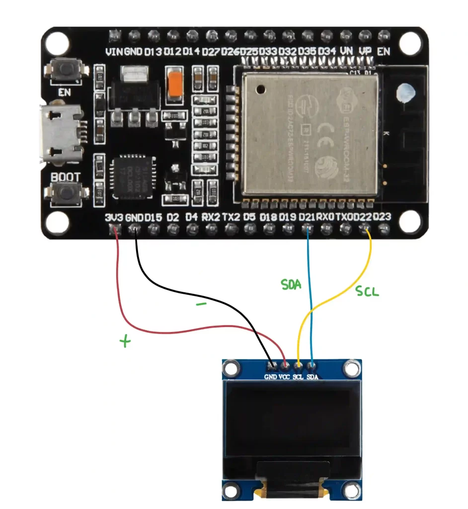
Here’s how to wire the OLED display to the ESP32:
| 1.3″ SH1107 OLED Display or SSD1306 0.9″ OLED Pins | Connect to ESP32 |
|---|---|
| VCC | 3.3V or 5V |
| GND | GND |
| SCL | GPIO 22 (Default I2C SCL) |
| SDA | GPIO 21 (Default I2C SDA) |
If your board uses different I2C pins, you’ll need to adjust the code accordingly. Both the displays I used have the same wiring diagram. They connect to the default I2C pins of the ESP32 board. If you are using any other board, look for the markings SDA and SCL. Connect them to the pins of the ESP32 as shown above the display should work.
3. Programming ESP32
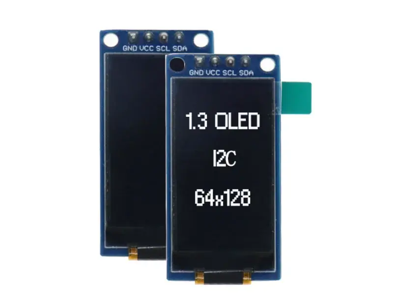
There are two different screens used in this project, which have different sizes. They look similar in design but need different libraries to work. Hence, I have written two different programs to show how to adapt the code for your own display. These OLEDs come in all types of shapes and sizes.
Install the libraries required for this project.
How to install libraries in Arduino easy way.
- Open Arduino IDE.
- Go to
Sketch > Include Library > Manage Libraries. - Search for each library and click
Install.
Make sure you have added ESP32 board support to Arduino IDE via Boards Manager. Then connect the ESP32 to Arduino IDE and upload the code.
Once the program is uploaded, it will connect to the Wifi hotspot that is set in the code. Once it is connected, ESP32 will print the IP Address in the serial monitor. This is important because we will need this to connect to the app. IP Address will be different for everyone and might change every time to make a new connection.
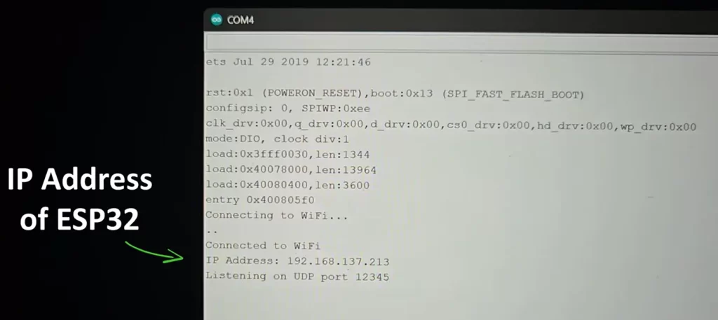
- Open the Serial Monitor (
Tools > Serial Monitor). - Set the baud rate to 115200.
- The ESP32 will attempt to connect to the WiFi network.
- Once connected, it will print the assigned IP Address. The default UDP port is 12345. Change it in the code if necessary.
- Use this IP for sending UDP packets to control the OLED display.
4. Breaking Down the Code
The code is super simple. Basically, ESP32 and the Android app need to connect to the same wifi hotspot to communicate. It does not need any internet. The app has a drawing area in which the user will sketch something. Every touch point on the screen has (x,y) values. These coordinates are sent to ESP32, where the program maps them to the OLED and draws the points.
The following example is for Oled_Draw_Wifi_1_3_inch, the code and logic are the same for Oled_Draw_Wifi_SSD1306, also known as 0.9″ OLED display only difference is the libraries. The app will work the same for both. You may use other displays, the app will work. The only thing that needs to change is the libraries for ESP32 code.
1. Import Libraries
#include <WiFi.h>
#include <WiFiUdp.h>
#include <Adafruit_GFX.h>
#include <Adafruit_SH110X.h>These include WiFi communication, UDP networking, and OLED graphics.
2. Define Settings
#define SCREEN_WIDTH 128
#define SCREEN_HEIGHT 64
#define OLED_RESET -1Tells the display how wide and tall it is, and that we aren’t using a hardware reset pin. If you have a different type of display, like 128X128, change the dimensions here. This is like setting the resolution of the screen.
const char* ssid = "ground";
const char* password = "12345678";Replace with your WiFi network details. Here we will define which Wifi network the ESP32 will connect to. There is no need for the internet; everything works on a local network, so the internet is not required.
3. Setup Function
display.begin(0x3C);        // Start OLED
display.setRotation(1); // Landscape modeInitializes and rotates the display for a better viewing angle. Here we will define the I2C address of the screen. The screens I used have the address 0x3C; your screen might have something else, so if the program does not work, then check the datasheet of the OLED for the correct I2C address
WiFi.begin(ssid, password); // Start WiFi
udp.begin(udpPort); // Start listening for UDPStarts WiFi and waits until you’re connected, and listens for UDP packets on port 12345.
4. Handle Incoming Data
int packetSize = udp.parsePacket();
char incomingPacket[255];
udp.read(incomingPacket, sizeof(incomingPacket) - 1);Checks if there’s a UDP packet.Reads the packet and stores it in a string.
sscanf(incomingPacket, "%d,%d,%d", &x, &y, &state);Parses the string into three integers: x, y, and state.
display.drawPixel(x, y, state ? SH110X_WHITE : SH110X_BLACK);
display.display();Turns a pixel ON or OFF depending on the state.
5. Full Code
#include <WiFi.h>                    // Include WiFi library for ESP32
#include <WiFiUdp.h>                // Include UDP support library
#include <Adafruit_GFX.h>           // Core graphics library
#include <Adafruit_SH110X.h>        // OLED display library for SH1107

// OLED display configuration
#define SCREEN_WIDTH 128            // OLED screen width in pixels
#define SCREEN_HEIGHT 64            // OLED screen height in pixels
#define OLED_RESET -1               // No reset pin used

// WiFi credentials
const char* ssid = "ground";        // Your WiFi network name
const char* password = "12345678";  // Your WiFi password

// UDP configuration
WiFiUDP udp;                        // Create a UDP object
const int udpPort = 12345;          // Port to listen for incoming UDP packets

// OLED display object: SH1107 display with 64x128 resolution
Adafruit_SH1107 display = Adafruit_SH1107(64, 128, &Wire);  // Width and height reversed due to rotation

void setup() {
  Serial.begin(115200);             // Start serial communication for debugging

  // Initialize OLED display
  display.begin(0x3C);              // Start the display at I2C address 0x3C
  display.clearDisplay();           // Clear the screen buffer
  display.display();                // Push buffer to screen
  display.setRotation(1);           // Rotate display so (0,0) is at top-left

  // Connect to WiFi
  WiFi.begin(ssid, password);       // Start WiFi connection
  Serial.println("Connecting to WiFi...");
  while (WiFi.status() != WL_CONNECTED) {
    delay(500);
    Serial.print(".");              // Print dots while waiting
  }
  Serial.println("\nConnected to WiFi");
  Serial.print("IP Address: ");
  Serial.println(WiFi.localIP());   // Print local IP once connected

  // Start listening for UDP packets
  udp.begin(udpPort);
  Serial.printf("Listening on UDP port %d\n", udpPort);
}

void loop() {
  // Check if there's an incoming UDP packet
  int packetSize = udp.parsePacket();
  if (packetSize) {
    char incomingPacket[255];       // Buffer to hold the incoming packet
    int len = udp.read(incomingPacket, sizeof(incomingPacket) - 1); // Read packet
    if (len > 0) {
      incomingPacket[len] = '\0';   // Null-terminate the string
    }

    // Parse the incoming data (expected format: "x,y,state")
    int x, y, state;
    sscanf(incomingPacket, "%d,%d,%d", &x, &y, &state); // Extract integers
    Serial.println(incomingPacket); // Print the raw packet

    // Draw pixel on OLED if it's within screen bounds
    if (x >= 0 && x < SCREEN_WIDTH && y >= 0 && y < SCREEN_HEIGHT) {
      display.drawPixel(x, y, state ? SH110X_WHITE : SH110X_BLACK); // Set or clear pixel
      display.display();         // Update the display
    }
  }
}
Full code can be downloaded from GitHub
5. How to Use
- Upload the program and connect to the hotspot
- Get the IP address of the ESP32 from the serial monitor
- Install the APK file on your phone
- Select the OLED drawing option
- Connect the phone to the same hotspot as the ESP32
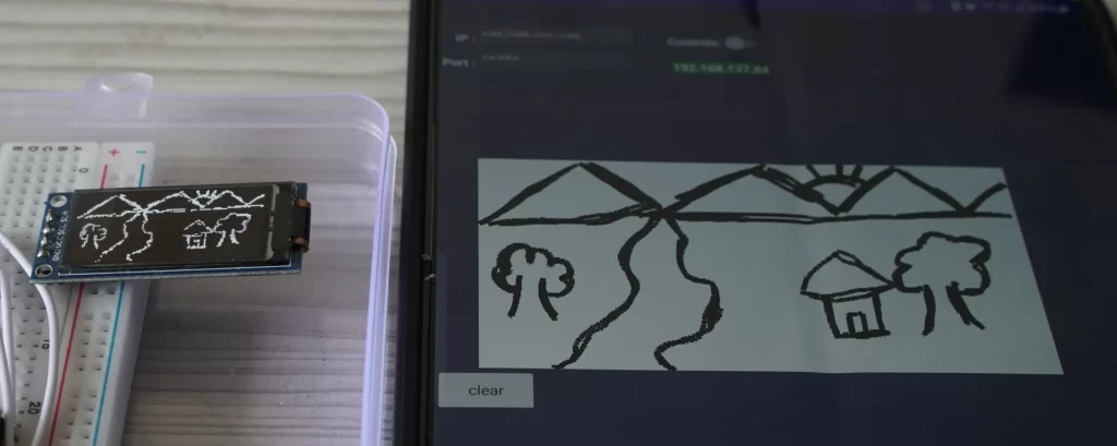
- Enter the ESP32 IP address and port
- Start drawing on the screen. If the connection is done properly, you will see output on the OLED screen.